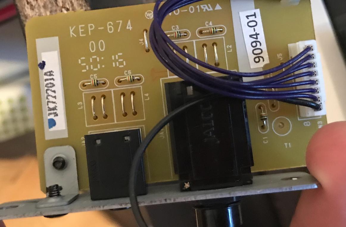
The cleanest solution is to create a new wire harness that will connect between the existing cable (after being unplugged) and the PCB. This will allow you to easily undo the modification simply by removing the new wire harness and plugging the original cable back into the PCB.
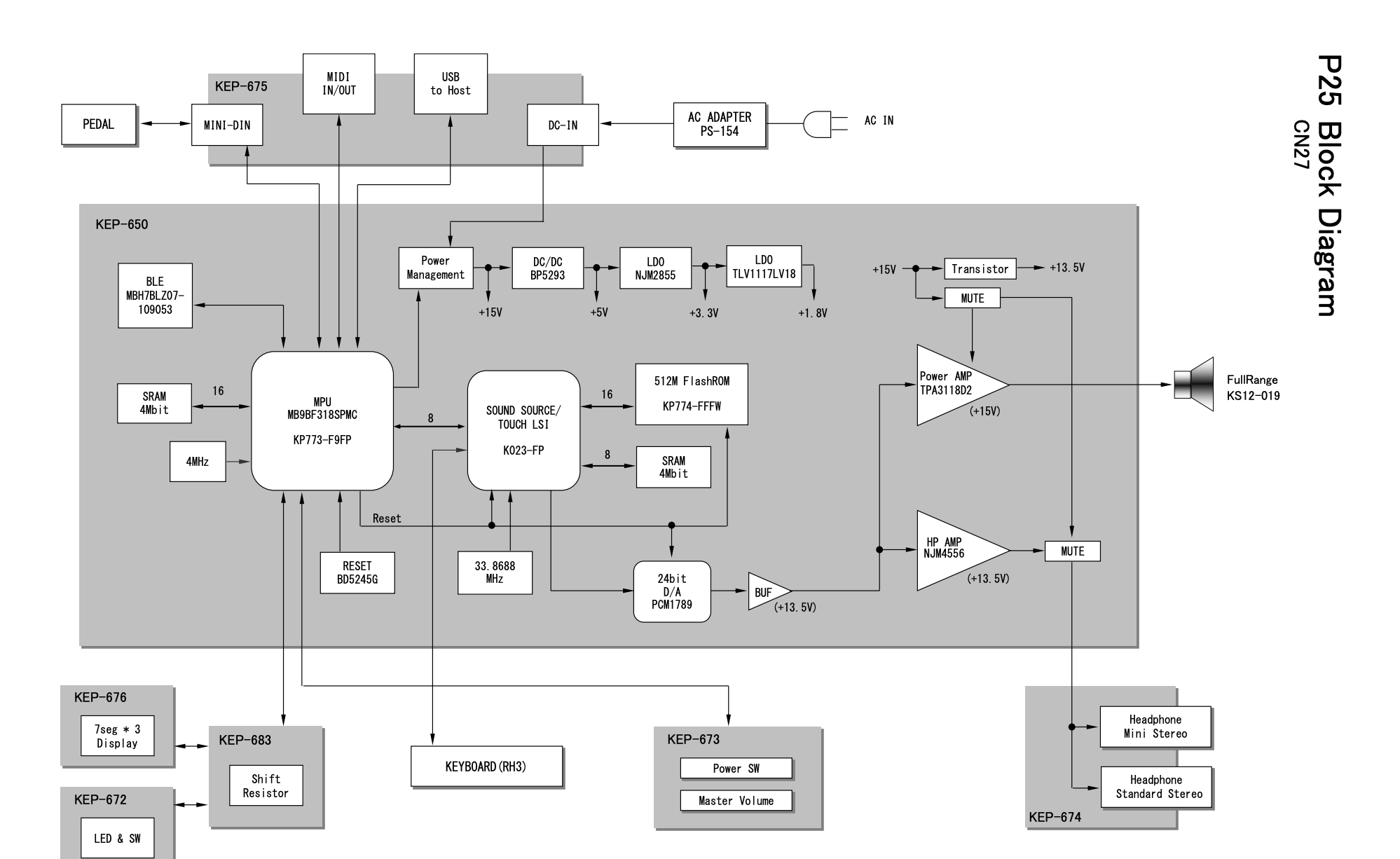
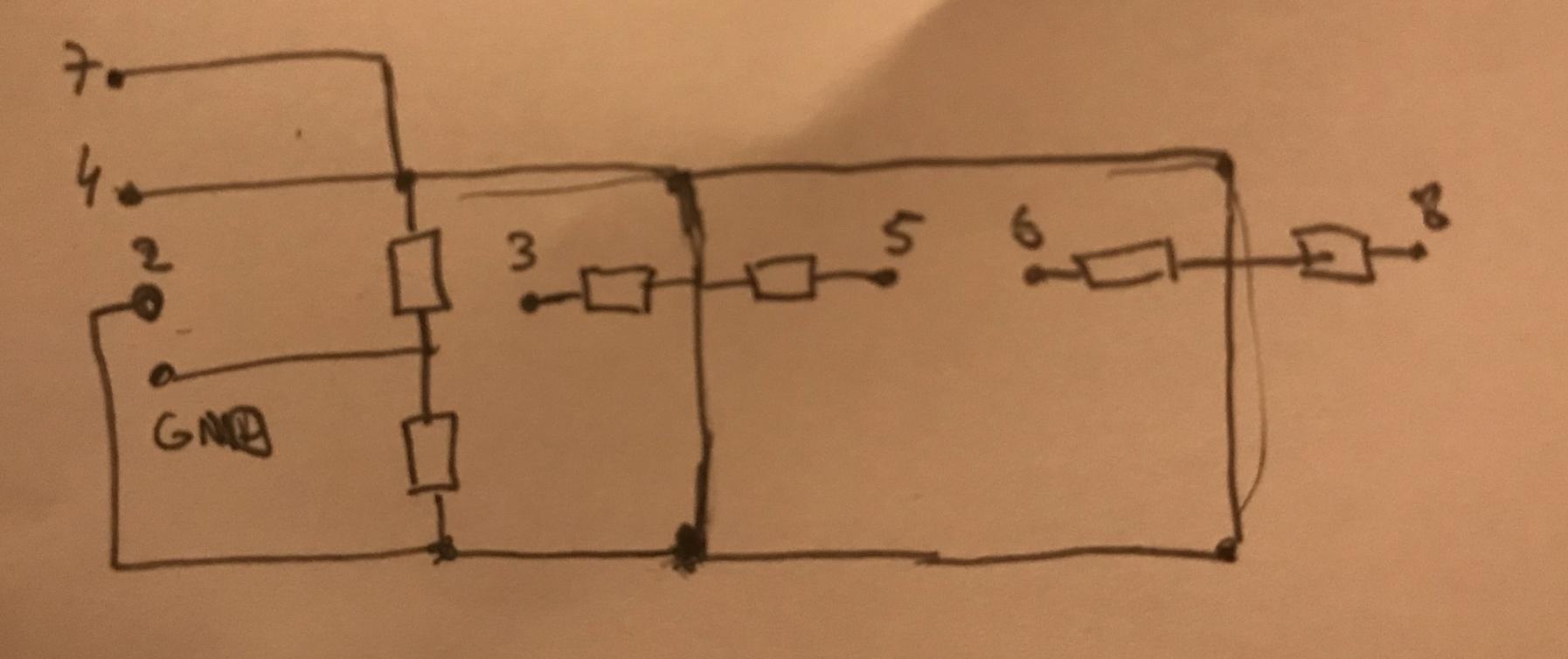
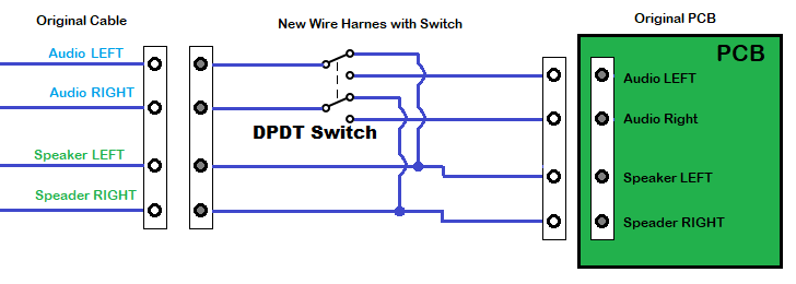
The new wire harness should contain a mating connector (with male pins) to attach to the original cable, a DPDT type switch to enable speakers even when headphones are plugged in, and a mating connector to the PCB. First you need to discover which pins in the cable are the audio source outputs (LEFT and RIGHT), and which pins are the speaker inputs (LEFT and RIGHT). All other pins should be connected straight through and not shown. Wire up the DPDT switch as shown below. This circuit will work while headphones are always plugged in. Switch in up position (as drawn) will connect to speakers, down position to headphones if inserted but speakers if not.
Note that with the headphones plugged in, the connections to the speaker through the PCB will be open (inside the socket) and not interfere with headphone use.
To answer your other questions:
How does the board know to turn on the speakers?
@user_1818839 already provided this answer. The audio sockets contain switch contacts that break and will disconnect the speakers when the plug is inserted.
What's the purpose of jumper wires 7 and 4 (J5 on the board)?
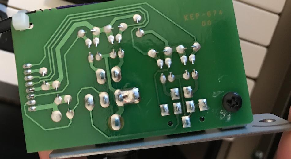
Since the PCB is single sided, the jumpers only serve as routing over existing PCB traces. Without them, the PCB traces would be more complicated, or not possible with a single layer. This allows for a lower cost since double sided would be more expense. To be clear, I'm referring to items J4, J5, and J7 (under wires in photo), not components L1, L2, etc.

