I'd like to protect my board mounted switching regulator's input from reverse polarity events without having to modify the existing run of boards we had created and populated. The primary regulator powers several of these boards that connect via pigtails down the line of cable coming off its 24V DC output.
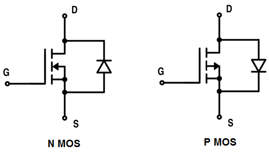
The vast majority of examples I see online use PFETs for a high-side switch configuration, although it is sometimes noted a low-side nFET configuration works as well. I opted for the latter nFET setup just for better part availability during this supply chain madness and also to have a wider array of options for FETs with a high Vgs. The board mounted switching regulator's input allows a range of 9-36 VDC, which is one of the reasons we chose it. The max input it will ever see is right around 30V, which is the maximum output adjustability that the fine adjust potentiometer on the primary (Vreg) allows. With the load regulation specs, it could technically jump +/- 1%, so I will likely need to ensure it is dialed down to roughly 28-29V. As all of this suggests, I am trying to keep the component count to 1 nFET (with minimum Vgs = +/-30V) because I would like to install this modification as an inline solution in series with the board's input wiring.
A couple questions about this design:
1.) I chose the nFET for parts options, but also because of low Rds (anecdotally). This is also an isolated circuit and the DC negative output from our primary regulator (Vreg) does not bond to any chassis ground or common node. Is it of any concern to proceed with this design? I only ask because of the pFET's popularity in reference material, but understand why people do it.
2.) Should I anticipate any issues with the load it's powering? It's not a purely resistive load, and the regulator it's powering also powers inductive loads itself (12V solenoid valves) as depicted. I am used to installing snubber diodes for the solenoids depicted, but I am uneducated as to the risks, perhaps at a smaller scale, of what the dangers would be after disconnecting the board mounted regulator at Vin. Where does the small amount of EMF bleed in this case? Wouldn't this cause a small reverse buildup (as -Vgs) of a few volts or so? Should I be placing an additional snubber in parallel with the nFET?
3.) Assuming this hasn't been a poor approach, what form factor product can I search for that provides an easier, more modular solution for placing FETs inline on the wire, similar to a fuse assembly?
Thanks for any suggestions.
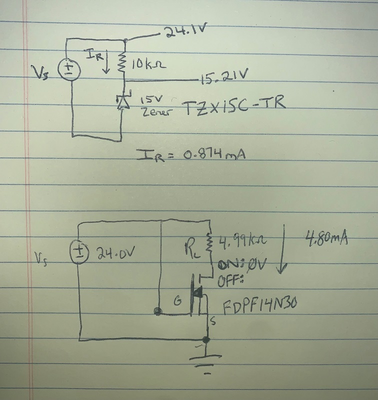
EDIT 1: Received parts, built circuit as depicted in reply, but with 15V Zener and a 10K resistor. FET used is FDPF14N30.
I was able to energize, reverse, then energize, and reverse again. After a few cycles of this, the circuit quit working. With the circuit removed, the regulator powers up again normally under normal wiring. What could have caused this? After observing the board mounted regulator kick back on and the equipment power back up normally, I did individual analysis on the components I'd used. The findings are below:


