With Verbal Kint's contribution, I'll expand on thoughts behind my earlier comment(s).
Notes from: "A Practical Method of Designing RC Active Filters"
I want to start out by reflecting on the TR-50 paper by R. P. Sallen & E. L. Key, dated 6 May 1954 (I'm not aware of a link on the web to it at this time.) This earlier edition is still controlled by the US Air Force but has been unclassified and has a more material in it than the abridged version that was published the next year, in 1955.
The authors focus' is on active networks, with active gain stages using vacuum tubes, and therefore only give a small nod towards passive networks (as a basis upon which to build these active network filters.) But they do provide some handy results to apply in parsing 2nd order transforms of the form (where \$a_i\$ and \$b_i\$ are all real, positive constants such that \$a_i\ge 0\$ and \$b_i\gt 0\$:
$$G_s = \frac{N_s}{D_s}=\frac{a_2s^2+a_1s+a_0}{b_2s^2+b_1s+b_0}$$
Given that, they focus on \$D_s\$ and provide that if \$\omega_{_0}=\sqrt{\frac{b_0}{b_2}}\$ and \$d=\frac{b_1}{\sqrt{b_2 \,b_0}}\$ (\$d=2\zeta\$ in modern usage), then \$D_s\$ can be factored as:
$$D_s=b_0\cdot\left[\left(\frac{s}{\omega_{_0}}\right)^2+d\cdot\left(\frac{s}{\omega_{_0}}\right)+1\right]$$
and where the zeros of \$D_s\$ (poles, when placed in the denominator) line on a circle with radius \$\omega_{_0}\$ with the real part at \$-\frac12 d\,\omega_{_0}=\zeta\,\omega_{_0}\$ in the under-damped case when \$\zeta\le 1\$. (The over-damped case has all the zeroes directly located on the negative real axis.)
The shape is determined solely by \$d\$ (or \$\zeta\$ or \$Q\$), while \$\omega_0\$ determines the positions of the zeroes in the frequency domain and \$b_0\$ is merely a relative amplitude value.
Q
Verbal Kint prefers (as I see it) the use of \$Q\$ over \$\zeta\$ or \$d\$. The relationship is: \$Q=\frac1{2\zeta}=\frac1{d}\$.
Which is preferred depends on where your brain is at, I think. I don't think of it as an always \$Q\$ or always \$\zeta\$ kind of thing.
When dealing with under-damped situations, I tend to think more in terms of \$Q\$.
When dealing with wide bandpass situations (over-damped, for sure) then I tend to think more in terms of \$\zeta\$.
And when it's just a matter of mathematics I tend to stick closely to \$\zeta\$ as I prefer that over fractions of the form \$\frac1{Q}\$, which is more of a pain when writing out equations.
Breaking Down Your Transfer function
In your case, \$a_2=8.4505\times 10^3\$, \$a_1=25.0724\times 10^9\$, \$a_0=61.2553\times 10^9\$, \$b_2=1\$, \$b_1=86.807\times 10^9\$, and \$b_0=1.3513\times 10^{15}\$. Then it is just a matter of following the above recipe:
$$\begin{align*}
&\text{Numerator} &&\text{Denominator}
\\\\
\omega_{_0}^{\:'}&=\sqrt{\frac{a_0}{a_2}\vphantom{\frac{b_0}{b_2}}}\approx 2.692\times 10^3 & \omega_{_0}&=\sqrt{\frac{b_0}{b_2}}\approx 36.76\times 10^6
\\\\
d^{\,'}=2\zeta^{\,'}&=\frac{a_1}{\sqrt{a_2 \,a_0\vphantom{b_2 \,b_0}}}\approx 1102.0 &d=2\zeta&=\frac{b_1}{\sqrt{b_2 \,b_0}}\approx 2361.5
\end{align*}$$
This results in the following:
$$\begin{align*}
G_s&=\frac{a_0}{b_0}\cdot\left[\frac{\left(\frac{s}{\omega_{_0}^{\:'}}\right)^2+d^{\,'}\left(\frac{s}{\omega_{_0}^{\:'}}\right)+1}{\left(\frac{s}{\omega_{_0}}\right)^2+d\left(\frac{s}{\omega_{_0}}\right)+1}\right]
\end{align*}$$
Before pursuing this as Verbal Kint did (I'll get to that in a later section), I'd like to follow through with a different process that leads to an interesting, separate result:
$$\begin{align*}
G_s&=\frac{a_0}{b_0}\cdot\left[\frac{\left(\frac{s}{\omega_{_0}^{\:'}}\right)^2+d^{\,'}\left(\frac{s}{\omega_{_0}^{\:'}}\right)+1}{\left(\frac{s}{\omega_{_0}}\right)^2+d\left(\frac{s}{\omega_{_0}}\right)+1}\right]
\\\\
&=\frac{a_0}{b_0}\cdot\left[\frac{\left(\frac{s}{\omega_{_0}^{\:'}}\right)^2}{\left(\frac{s}{\omega_{_0}}\right)^2+d\left(\frac{s}{\omega_{_0}}\right)+1}+\frac{d^{\,'}\left(\frac{s}{\omega_{_0}^{\:'}}\right)}{\left(\frac{s}{\omega_{_0}}\right)^2+d\left(\frac{s}{\omega_{_0}}\right)+1}+\frac{1}{\left(\frac{s}{\omega_{_0}}\right)^2+d\left(\frac{s}{\omega_{_0}}\right)+1}\right]
\\\\
&=\frac{a_0}{b_0}\cdot\left[\frac{\left(\frac{\omega_{_0}}{\omega_{_0}^{\:'}}\right)^2\left(\frac{s}{\omega_{_0}}\right)^2}{\left(\frac{s}{\omega_{_0}}\right)^2+d\left(\frac{s}{\omega_{_0}}\right)+1}+\frac{\left(\frac{\omega_{_0}}{\omega_{_0}^{\:'}}\right)\left(\frac{d^{\,'}}{d}\right)d\left(\frac{s}{\omega_{_0}}\right)}{\left(\frac{s}{\omega_{_0}}\right)^2+d\left(\frac{s}{\omega_{_0}}\right)+1}+\frac{1}{\left(\frac{s}{\omega_{_0}}\right)^2+d\left(\frac{s}{\omega_{_0}}\right)+1}\right]
\\\\
&=\frac{a_2}{b_2}\frac{\left(\frac{s}{\omega_{_0}}\right)^2}{\left(\frac{s}{\omega_{_0}}\right)^2+d\left(\frac{s}{\omega_{_0}}\right)+1}+\frac{a_1}{b_1}\frac{d\left(\frac{s}{\omega_{_0}}\right)}{\left(\frac{s}{\omega_{_0}}\right)^2+d\left(\frac{s}{\omega_{_0}}\right)+1}+\frac{a_0}{b_0}\frac{1}{\left(\frac{s}{\omega_{_0}}\right)^2+d\left(\frac{s}{\omega_{_0}}\right)+1}
\end{align*}$$
The last result above is what's important. It converts what appears to be an abstract and somewhat impenetrable pair of 2nd order polynomials into the key ideas required to understand their combined behaviors. (The first term is a high-pass, the middle term is a band-pass, and the final term is a low-pass and the gains for each are separated out, now.)
Note that it also now becomes more obvious why \$a_i\$ can be zero while \$b_i\$ cannot be.
As you can see, the whole thing breaks into a nicely expressed standard form.
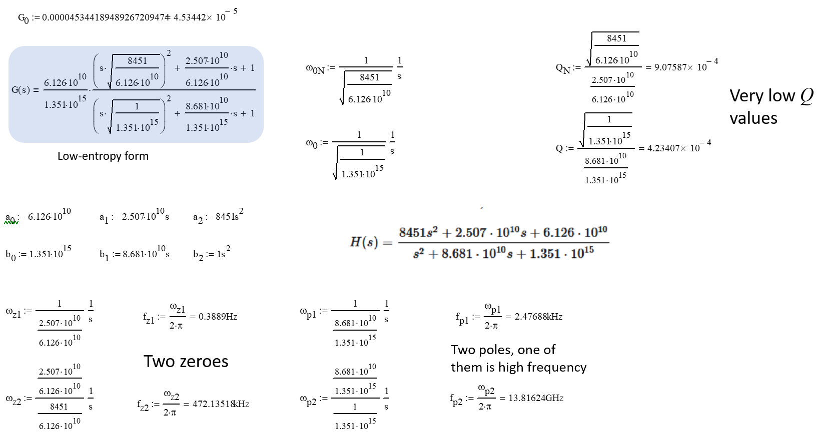
And this is where I got the gain factors for my earlier comment: \$\frac{a_2}{b_2}\approx 8.5405\:\text{k}\$, \$\frac{a_1}{b_1}\approx 288.83\:\text{m}\$ and \$\frac{a_0}{b_0}\approx 45.331\:\mu\$ (this last one is Verbal Kint's \$G_0\$.)
You can feel free to replace \$d\$ with either \$2\zeta\$ or \$\frac1{Q}\$. Doing that and multiplying everything by \$\frac{\omega_{_0}^{\:2}}{\omega_{_0}^{\:2}}\$ yields:
$$\begin{align*}
G_s&=\frac{a_2}{b_2}\cdot\frac{s^2}{s^2+2\zeta\,\omega_{_0}s+\omega_{_0}^{\:2}}+\frac{a_1}{b_1}\cdot\frac{2\zeta\,\omega_{_0}s}{s^2+2\zeta\,\omega_{_0}s+\omega_{_0}^{\:2}}+\frac{a_0}{b_0}\cdot\frac{\omega_{_0}^{\:2}}{s^2+2\zeta\,\omega_{_0}s+\omega_{_0}^{\:2}}
\end{align*}$$
Which is the other standardized form and the one I indicated in comments, earlier.
A Short Note
More commonly, a transfer function only includes one of the above three terms and is either entirely a low-pass, entirely a high-pass, or entirely a band-pass transfer function.
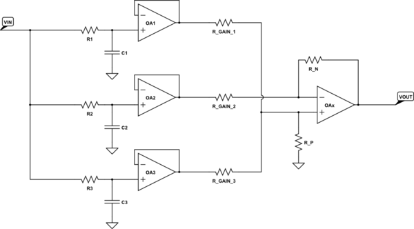
But either of these simpler passive networks will result in a transfer function that includes all three terms:

simulate this circuit – Schematic created using CircuitLab
Other arrangements with different elements can be readily produced. But the above are, in my mind anyway, two of the simplest ones using ideal components that can get you there.
Roots
Let's return to (I promised to get back to Verbal Kint's answer):
$$\begin{align*}
G_s&= \frac{a_0}{b_0} \cdot
\left[
\frac{
\left( \frac{s}{\omega_{_0}^{\:'}} \right)^2+d^{\,'}\left( \frac{s}{\omega_{_0}^{\:'}} \right) + 1
}{
\left(\frac{s}{\omega_{_0}}\right)^2+d\left(\frac{s}{\omega_{_0}}\right)+1
}
\right]
\end{align*}$$
Verbal Kint specified that \$G_0=\frac{a_0}{b_0}\$ and focused his attention upon on the roots. In the over-damped case (your numerator and denominator are both way over-damped) the solutions are:
$$\begin{align*}\text{zeros}\left\{\begin{array}{l}s_1&=-\omega_{_0}\left(\zeta-\sqrt{\zeta^2-1}\right)&\text{and}& \omega_{_\text{L}}=-s_1\\s_2&=-\omega_{_0}\left(\zeta+\sqrt{\zeta^2-1}\right)&\text{and}& \omega_{_\text{H}}=-s_2 \end{array}\right.\end{align*}$$
In the over-damped case, both \$\omega_{_\text{H}}\$ and \$\omega_{_\text{L}}\$ are real-valued. So, the transfer function can also be written out as:
$$\begin{align*}
G_s&=G_0\cdot\left[\frac{\left(1+\frac{s}{\omega_{_\text{L}}^{\:'}}\right)\left(1+\frac{s}{\omega_{_\text{H}}^{\:'}}\right)}{\left(1+\frac{s}{\omega_{_\text{L}}}\right)\left(1+\frac{s}{\omega_{_\text{H}}}\right)}\right]
\end{align*}$$
Computing the values I find:
$$\begin{align*}
\omega_{_\text{L}}^{\:'}&\approx 2.44314 &f_{_\text{L}}^{\:'}&\approx 388.83\:\text{mHz}
\\
\omega_{_\text{H}}^{\:'}&\approx 2.96697\times 10^6& f_{_\text{H}}^{\:'}&\approx 472.208\:\text{kHz}
\\
\omega_{_\text{L}}&\approx 15.5667\times 10^3 &f_{_\text{L}}&\approx 2.47752\:\text{kHz}
\\
\omega_{_\text{H}}&\approx 86.807\times 10^9 &f_{_\text{H}}&\approx 13.816\:\text{GHz}
\end{align*}$$
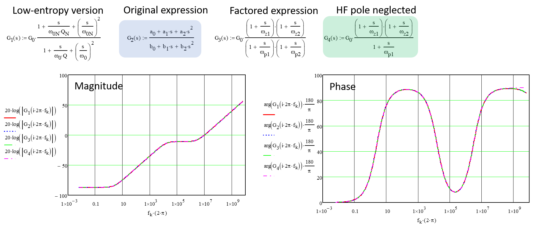
Note that Verbal Kint asked you if \$\omega_{_\text{H}}\approx 13.816\:\text{GHz}\$ is useful as a pole. It's probably not as its factor is very, very close to 1 for any frequency most of us encounter. (Of course, you can't just drop it out without also then being forced to modify the numerator in some reasonable way, as well. You don't get to have numerator that is a higher order than the denominator.)
Relationships between \$\omega_{_\text{H}}\$, \$\omega_{_\text{L}}\$, and \$\zeta\$
For the over-damped situation, it turns out that \$\omega_{_\text{H}}\$ and \$\omega_{_\text{L}}\$ relate directly to \$\zeta\$:
$$\zeta=\frac12\frac{\omega_{_\text{L}}+\omega_{_\text{H}}}{\sqrt{\omega_{_\text{L}}\cdot \omega_{_\text{H}}}}=\frac12\frac{\omega_{_\text{L}}+\omega_{_\text{H}}}{\omega_{_0}}$$
It's pretty easy to see that as \$\omega_{_\text{L}}\to \omega_{_\text{H}}\$ then \$\zeta\to 1\$. But for \$\omega_{_\text{H}}\gg \omega_{_\text{L}}\$, then \$\zeta\to \frac12\sqrt{\omega_{_\text{H}}}\$.
It follows that wide bandwidth 2nd order filters tend to have large values for \$\zeta\$ (and therefore very small values for \$Q\$.) This fact helps in designing such filters. If \$\zeta\$ is large, then the design will tend towards using separate low-pass and high-pass filters, as separate sections that are concatenated. However, if \$\zeta\$ is small (\$Q\$ is larger), then the design will tend towards a unified bandpass design, instead.
There are a couple of interesting terms used to describe the fractional bandwidth of a system. One is \$B_{_\text{F}}=\frac{\omega_{_\text{H}}-\omega_{_\text{L}}}{\omega_{_0}}\$. The other is \$B_{_\text{F}}^{\:'}
=2\frac{\omega_{_\text{H}}-\omega_{_\text{L}}}{\omega_{_\text{H}}+\omega_{_\text{L}}}\$. These are related to each other in this way: \$B_{_\text{F}}=\zeta\cdot B_{_\text{F}}^{\:'}\$. It turns out that \$0 \le B_{_\text{F}}^{\:'}\le 2\$ but that \$B_{_\text{F}}\to \sqrt{\frac{\omega_{_\text{H}}}{\omega_{_\text{L}}}}\$ for large ratios of \$\frac{\omega_{_\text{H}}}{\omega_{_\text{L}}}\$.
Just be aware that fractional bandwidth doesn't have a single definition in the literature.
Summary
I'm still wondering what passive network you imagine duplicating your original transfer function. (The comment expression you gave certainly doesn't cut it.) Though perhaps you had also simplified your expression?
I remain curious and interested. Draw out a schematic and provide part values. Not another equation. I'd like to see the topology and details and I'll work out the transfer equation on my own.
But I suspect that by hacking things around, you did in fact find functions that were usefully close to the original and felt you had succeeded. (Not strictly as a matter of mathematics but as a practical matter.) If so, all you likely did is, by trial and error, find a usefully simplified expression.
I think Verbal Kint was trying to move you towards a similar place but through a rigorous mental approach rather than trial and error.
Added Notes Per Comments from OP
If I understand correctly, this applies to voltage transfer functions.
No, it applies to all transfer functions. In voltage-in/voltage out cases the units are \$\frac{V}{V}\$, which can be treated as unitless. But in cases where the input units are current, for example, and the output is voltage then the gain value will carry units (Ohms, for example.)
However, my example is about the output impedance, described via
transfer function H(s) (apologize if this is not the right
nomenclature) which I want to find an equivalent circuit. I am not
sure if active filter design relates to this.
Again, you can have a gain with units, such as Ohms. For example, suppose the following case:

simulate this circuit
The transfer function is:
$$\begin{align*}
G_s&=A\cdot\left[\frac{1}{\left(1+\frac{s}{\omega_{_\text{L}}}\right)\left(1+\frac{s}{\omega_{_\text{H}}}\right)}\right]
\end{align*}$$
In this case, \$A=\frac{R_1\,R_4}{R_1 + R_2 + R_3 + R_4}\$ and the units are definitely \$\Omega\$.
I am not sure if active filter design relates to this.
The mathematics approach is similar. I'm not sure there's a problem. But I suppose you can identify one?
Does this apply to an output impedance as well?
Yes. As indicated above.
I don't mind the exact structure of the equivalent passive circuit, I
just want to be able to draw it. Could be a ladder, shunt networks or
similar.
Then perhaps you should refer to Verbal Kint's reference here.
I don't want to provide, nor do I have the time or inclination to do so, a general approach for arbitrary order. I'm not sure one exists as I imagine the set of possible answers has often more than one item in it. I don't believe such a proof exists, but if you can prove that there is always one and only one possible answer in the set, I may yet give it a hack. But I'll need to see the mathematical proof before I bother.


