1
\$\begingroup\$

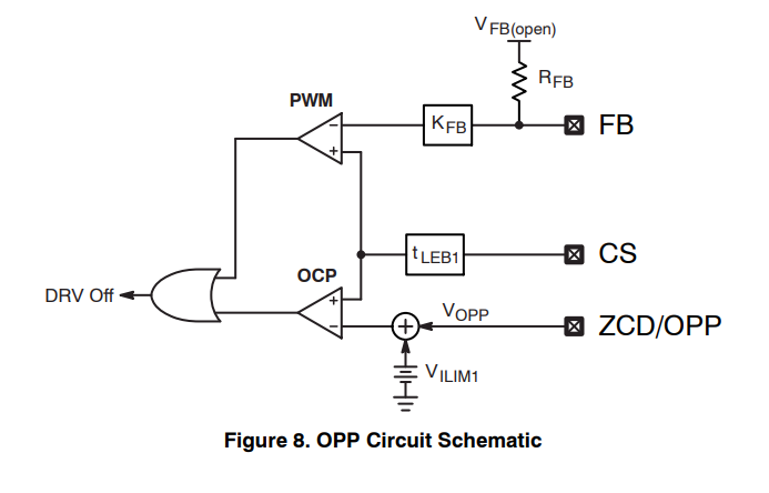
About NCP1342, there is a protection circuit which was called Overpower Protection (on page 14).

I am confused about why this is over-power protection. There is no circuit to do the multiplication, I mean I·V = P, so how does this circuit know the power is higher or lower?

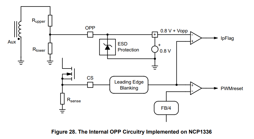
enter image description here

I also researched other DS from ONSEMI, I think both are the same.

Could someone explain this circuit to me?

enter image description here

\$\endgroup\$
3
  • 3
    \$\begingroup\$ Did you read the text describing how OPP works on pages 14 and 15? \$\endgroup\$
    – Justme
    Commented Aug 6, 2022 at 10:22
  • 1
    \$\begingroup\$ There's an auxillary winding on the primary side that generates a negative voltage proportionate to the rail voltage. A scaled down version of this negative voltage is used to compensate the current sense voltage. So as rail voltage goes up, the current limit goes down. \$\endgroup\$ Commented Aug 6, 2022 at 10:27
  • \$\begingroup\$ Hi @Justme, Yes, I read it several time, but still can't understant it. \$\endgroup\$
    – Power JJ
    Commented Aug 6, 2022 at 15:18

1 Answer 1

3
\$\begingroup\$

The method you propose could be an option but it is complicated to implement in an integrated circuit. You would need to sense the input current and voltage then do a multiplication and compare it with a maximum value. This is technically complicated - multiplier are not simple cells - and costly silicon- and components-wise. One way to overcome this is to observe the feedback voltage which is representative of the peak current hence the transmitted power. Actually, what is wanted is not exactly the absolute power value that the converter delivers, but more a limit of the maximum power the load can see in low- and high-line conditions, when the current sense setpoint hits the maximum limit.

It is a known fact that switching converters deliver more power at high line than at low line: peak current overshoot due to propagation delays, transition from CCM to DCM, higher switching frequency in QR etc. This is covered in a 4-part series of articles I published in How2Power entitled The Over-Power Phenomenon In DCM/CCM-Operated Flyback Converters. This phenomenon is exacerbated in a QR converter as shown in the below figure:
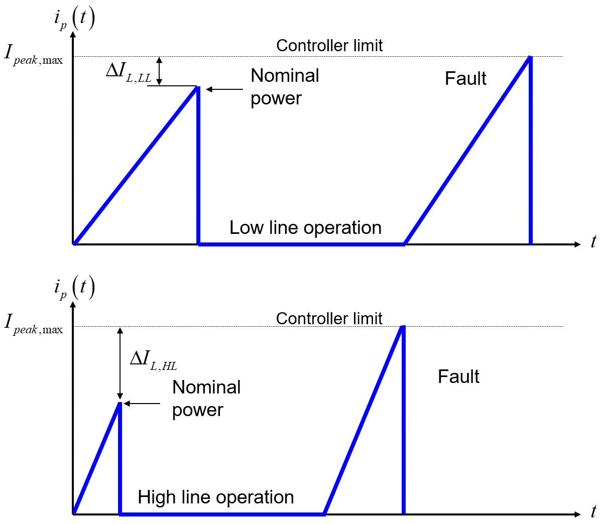
enter image description here

You see that in low-line conditions, you will design to have some margin so that the converter delivers its nominal power while the peak current is still below the limit. The switching frequency is the lowest. Should you increase the power slightly, the peak will soon touch the limit and protection will trip. Now, power the converter from a high-line input and the frequency increases for the same nominal power than at low line. As a result, the operating peak current is naturally much smaller. As the picture shows, the peak is now far away from the limit and you could deliver much more power before tripping the protection. This is an issue for the semiconductors and various components but for the downstream load as well in case of failure. What you need is a way to reduce this peak excursion between low- and high-line operations. This is called over-power protection or OPP.

You can do this through different methods - some are proprietary - like offsetting the current-sense voltage in relationship with the rectified bulk or, as proposed in the circuits you mentioned, use the negative voltage present on the auxiliary winding during the on-time:

enter image description here

This negative voltage depends on the transformer turns ratio for the auxiliary winding and the rectified bulk voltage. It will be low at low line and much higher at the maximum input (a ratio of 3 from 120 to 370 V). If you add this negative voltage to the positive peak current setpoint of 0.8 V for instance, then you see that you almost have the maximum peak current at low line but much lower in high-line conditions. As the pictures shows, it nicely keeps the maximum power under control which is mandatory for passing the limited power source tests or LPS.

\$\endgroup\$
8
  • \$\begingroup\$ Hi @Verbal Kint, Do you mean that when the voltage is a high line, the Vopp is higher (negative), so 0.8+Vopp will be small, and then the current setup point will be reduced? How do determine the 0.8V in the circuit? if we can increase the voltage and we can have more high current. any reason ONSEMI choose 0.8V? From your two figures, I can know the High Line will have a large margin than the Low line, but why it will run into fault? is the transient reason? \$\endgroup\$
    – Power JJ
    Commented Aug 6, 2022 at 16:40
  • 1
    \$\begingroup\$ Hi @PowerJJ, originally, the UC384x had 1 V as a maximum setpoint but it brings losses across the sense resistance. Onsemi has adopted 0.8 V which helps efficiency-wise and I think NXP uses 0.5 V which is even better. The smaller the voltage the best the efficiency but the worse the noise susceptibility of course. It goes into fault if you increase the load current until the setpoint touches the maximum limit of 0.8 V. \$\endgroup\$ Commented Aug 6, 2022 at 17:14
  • \$\begingroup\$ Hi @Verbal Kint, Thanks. I see. One more question, could you explain the Mathcad figure? What is compensated and uncompensated mean? \$\endgroup\$
    – Power JJ
    Commented Aug 7, 2022 at 1:31
  • \$\begingroup\$ Hi @PowerJJ, uncompensated means a converter without OPP and compensated means the same converter with OPP turned on. \$\endgroup\$ Commented Aug 7, 2022 at 20:01
  • \$\begingroup\$ Hi @Verbal Kint, I read your paper, and have some questions: In an ideal situation, the output power should be the same during the Low Line or High Line, right? If we don't control it, the Low Line and High Line power will have a large gap. 1. What happens if we have a large gap between HL and LL? 2. if we compensate for it, in the ideal situation, no efficiency drop, and the output power at the HL and LL should be the same, but in practice, the efficiency is different in HL and LL, so after the compensation, we sill can see the different power in the HL and LL, is it correct? \$\endgroup\$
    – Power JJ
    Commented Aug 8, 2022 at 5:51

Your Answer

By clicking “Post Your Answer”, you agree to our terms of service and acknowledge you have read our privacy policy.

Not the answer you're looking for? Browse other questions tagged or ask your own question.