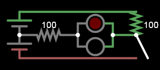
1
\$\begingroup\$

At a science museum today my kids and I visited an electricity challenge. First they were given a battery pack with two AA cells, a DC motor, a few lamps and switches, and a bunch of little jumper wires with alligator clips. They were allowed to build with these for a time. Eventually, once they had made a few circuits and it was obvious that they were enjoying the materials, the museum guide came over and gave us a challenge.

She gave us only these components:

  • 1 battery pack with 2 AA cells (3v)
  • 1 push-button switch (single pole, normally-open, momentary - a plain old switch)
  • 2 "LED units" (LED unit is in quotes because each of these LED units had both a red and green LED. These LEDs were internally wired so that one of the LEDs would come on regardless of which of the unit's two terminals were connected to positive. There was obviously a small resistor within the unit as well. The LED units had two terminals and they were not intended to be taken apart.)
  • unlimited jumper wires with alligator clips.

She set us this challenge:

  • Arrange the components so that initially one LED unit is on; when the button is pressed, it should turn off and the other should turn on.

After a good while of trying, we asked for her to show us, but in the end she couldn't remember how she had seen it done. I've been thinking of it all afternoon. Was it possible to use one single switch to toggle between two LED units? I think no and would love to know if there was some ingenious trick that would be possible.

Assume that you can't use any other components such as more switches, and that you aren't allowed to take the LED units apart or anything like that.

Assume that the yellow box shown below is [my best guess] what each LED unit looks like. The two terminals are the only points you can connect to.

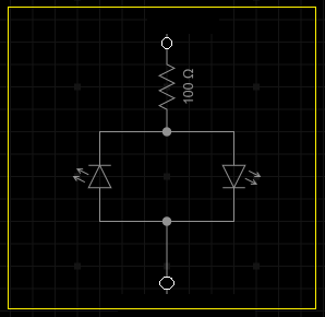
enter image description here

\$\endgroup\$
5
  • \$\begingroup\$ What color where the leds? The answers below are not wrong, but there could be another depending on the forward voltage drops. \$\endgroup\$
    – Passerby
    Commented Sep 5, 2022 at 3:10
  • \$\begingroup\$ Green in one direction, red in the other. Based on the presenter's other questions, I doubt she was thinking of taking advantage in the difference in forward voltage drops. This came right after "can you make two lights turn on?" \$\endgroup\$
    – nuggethead
    Commented Sep 5, 2022 at 3:12
  • \$\begingroup\$ @nuggethead I have answered the question assuming the differing voltage drops, but the lack of a resistor or much smaller battery/cells instead would make it non-funcional and would burn out the LEDs, as you know. \$\endgroup\$ Commented Sep 5, 2022 at 3:25
  • \$\begingroup\$ Yes, edins answer is my suggestion. Many green leds are 3.3V and would be fine at 3V with no resistor or even lower with. \$\endgroup\$
    – Passerby
    Commented Sep 5, 2022 at 4:31
  • \$\begingroup\$ It would be easy enough with a DPDT switch, not so much with a single-pole \$\endgroup\$
    – Frog
    Commented Sep 5, 2022 at 4:35

4 Answers 4

4
\$\begingroup\$

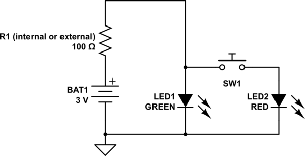
That would be very easy if you had a resistor included: since red LEDs generally need a lower voltage (1.5-1.9V) to run compared to the green LEDs (1.9-2.4V), all you need to do is turn one of them so that it lights green, and the other in parallel to it so that at that same polarity it turns red. Connect them together to the battery at either end (positive or negative), but on the other side connect the green one to the resistor and the resistor to the other side of the battery. Now just wire the switch between those two LEDs on that other side where they are not connected together, and the green should be on until you push the switch and the red turns on and drives green off. Here is a schematic, just note that the resistor can be either an external, extra component, or may simply represent the internal resistance of the battery (the two AA cells in series):

schematic

simulate this circuit – Schematic created using CircuitLab

I can't think of another way right now, and the lack of external resistor worries me. Had she given you the 3V coin cell, it would have had sufficient internal resistance for this circuit, but the AA batteries alone would let too much current through, which would make this circuit not work as intended, and would burn the LEDs out.

EDIT: Thanks to @BruceAbbott for reminding me of what I thought but forgot to add later on, namely that those batteries/cells would be fairly drained and have significantly higher internal resistance after all the playing around with lamps and motors, so there is a good chance it would have worked, but it's not guaranteed.

EDIT #2: As the OP reminded me, this would not work in his situation because the dual color double-LED units he has actually have built-in resistors, meaning that the voltages across the 2 units would be too close to notice the difference, due to their voltage drops becoming more linear because of the built-in resistors. If the task was remembered correctly (if something wasn't omitted in the question), this is good brain-teaser.

\$\endgroup\$
3
  • \$\begingroup\$ " but the AA batteries alone would let too much current through" - unless they were almost empty. I did an experiment with a red and blue LED, both with 100 ohm resistors in series as the OP suggested. On 3V, 50 ohms in the positive lead was enough make the blue LED go out when the button was pressed. \$\endgroup\$ Commented Sep 5, 2022 at 7:24
  • \$\begingroup\$ Unfortunately, I didn't have the ability to insert a switch at this position. See yellow box above \$\endgroup\$
    – nuggethead
    Commented Sep 5, 2022 at 9:54
  • \$\begingroup\$ @BruceAbbott Exactly, that's what I thought but forgot to add later on. You would figure that those batteries would be fairly drained and have significantly higher internal resistance after all the other tests, so there is a good chance it would have worked, but it's not guaranteed. \$\endgroup\$ Commented Sep 5, 2022 at 11:21
2
\$\begingroup\$

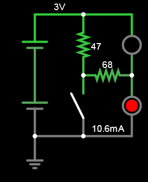
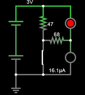
Before question was revised with schematic image.

enter image description hereenter image description here

After

You also did not specify how bright they have to be nor if the green was GaP green which are 2V LEDs but here at 1% of the full intensity on 1.5V, this works.

enter image description here

enter image description here

\$\endgroup\$
10
  • \$\begingroup\$ I don't think the LED unit I used was set up like this. I appreciate that you could build a toggle with a single switch this way, but I suspect the unit was more like the one shown in the question. It's a recent edit. \$\endgroup\$
    – nuggethead
    Commented Sep 5, 2022 at 3:03
  • \$\begingroup\$ you added the photo after my answer \$\endgroup\$
    – D.A.S.
    Commented Sep 5, 2022 at 4:01
  • \$\begingroup\$ Yes, I added it after. I didn't have access to the point between the batteries, though. I think it was not a solvable challenge \$\endgroup\$
    – nuggethead
    Commented Sep 5, 2022 at 9:52
  • \$\begingroup\$ Unfortunately even this revised answer doesn't satisfy the conditions of the challenge. There are two complete LED units, each with two LEDs in reversed orientation. This has just one, plus an extra resistor. \$\endgroup\$
    – nuggethead
    Commented Sep 5, 2022 at 11:10
  • \$\begingroup\$ It was ambiguous to toggle the "other one". Other colour, side or lamp? Just put both together inverted \$\endgroup\$
    – D.A.S.
    Commented Sep 5, 2022 at 11:15
1
\$\begingroup\$

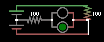
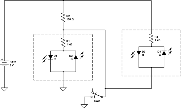
I can do it with the motor added. Otherwise, I don't think it is possible. In the below R2 represents the motor.

schematic

simulate this circuit – Schematic created using CircuitLab

\$\endgroup\$
5
  • 2
    \$\begingroup\$ Nope, no motor allowed. I also suspected it simply couldn't be done without more components and she was mistaken. Perhaps she saw someone else make a circuit like your suggestion and forgot that they had included the motor. \$\endgroup\$
    – nuggethead
    Commented Sep 5, 2022 at 3:13
  • 2
    \$\begingroup\$ Yes, that's my suspicion. Not a great puzzle to give kids if there is no solution. \$\endgroup\$ Commented Sep 5, 2022 at 3:37
  • \$\begingroup\$ Agreed! They took it well \$\endgroup\$
    – nuggethead
    Commented Sep 5, 2022 at 9:50
  • 1
    \$\begingroup\$ Your answer actually arranges the LED units and the switch properly, considering their built-in resistors which make my solution unworkable. The addition of the motor also makes more sense because the LEDs would indicate an open or closed switch with a running motor, so it is likely the guide mistakenly omitted the motor. \$\endgroup\$ Commented Sep 6, 2022 at 7:24
  • 1
    \$\begingroup\$ This solution will work within the constraints of the problem statement: since there are an "unlimited number" of jumper wires available, each with some nominal resistance, just replace the motor with enough jumpers in series to get about 100 ohms! \$\endgroup\$
    – td127
    Commented Sep 8, 2022 at 18:05
1
\$\begingroup\$

No, it's not possible. Other answers make various suggestions, but not meet the narrow specifications of the challenge.

I think Spehro's answer is closest to guessing why the well-meaning guide made suggestion. It should indeed be possible using the motor, functioning like an external resistor. I suspect she saw it done this way and simply forgot the motor was involved.

But with the exact components given and the inability to connect to anywhere but the two terminals of the LED unit as described, it cannot be done.

\$\endgroup\$

Your Answer

By clicking “Post Your Answer”, you agree to our terms of service and acknowledge you have read our privacy policy.

Not the answer you're looking for? Browse other questions tagged or ask your own question.