tl; dr: wide regulator output range is hard, if not impossible, to achieve with a microcontroller voltage DAC control. It’s more feasible (and repeatable) with a current DAC.
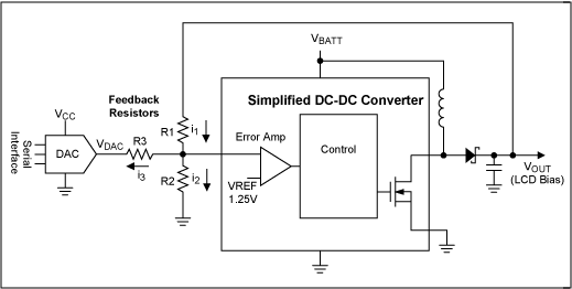
If you insist, here’s how to move through. First, remember that the FB node will always be Vref. Use Kirchhoff Current Law to work out the formulas for each resistor current to/from the FB node. Then, formulate this in a spreadsheet and experiment with different resistor values. That’s a basic design procedure.
Maxim app note that includes the math: https://www.maximintegrated.com/en/design/technical-documents/tutorials/8/818.html
Alternately, model it in Falstad with an op-amp standing in for the regulator.
How does the DAC work to set the voltage? The current to/from the DAC will be into Vref. The DAC will interact with FB and the output voltage as follows:
- DAC voltage higher than Vref, sources current into FB and drives the output voltage down
- DAC voltage lower than Vref, sinks current and drives the voltage up
Now here’s the thing. To achieve a range that includes a high-ish output voltage (30V, say), the DAC has to sink enough current to GND to get the job done. The higher the desired output voltage, the more current it needs to sink. Also, if the DAC itself doesn’t swing all the way to GND that can also work against you.
Scaling the feedback pair to their highest feasible values makes this more achievable. The regulator datasheet will tell you recommended values for R1 and R2. Pay close attention here: there may be some feedback loop stuff that depends on it.
Your attempt to minimize DAC current could result in a feedback pair of such high values that your circuit will suffer other problems, including inaccuracy due to bias current, instability or poor transient response.
My guess is that it won’t achieve 30V because the DAC won’t be able to sink enough current, or swing to a low enough voltage. You could remedy this by adding a buffer or perhaps a voltage-to-current conversion circuit.
Or you can use a DS4432 and call it good. This is what I suggested in the answer you reference.
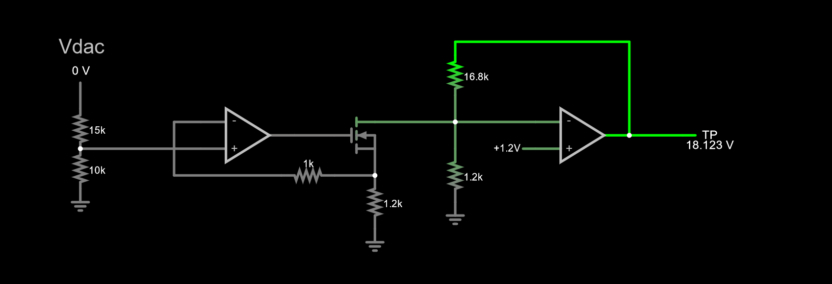
BONUS: DAC control with a voltage-controlled current sink. Default voltage about 18V. Adjust as needed. Simulate it here.
A major benefit of this circuit is that the DAC will tend to power on at zero, or possibly, high-Z. Either way, this will result in the lowest output (default) voltage. The op-amp only needs to swing in the region of FET threshold, so 1.5V or so, although the LMV321 will work just fine.


