2
\$\begingroup\$

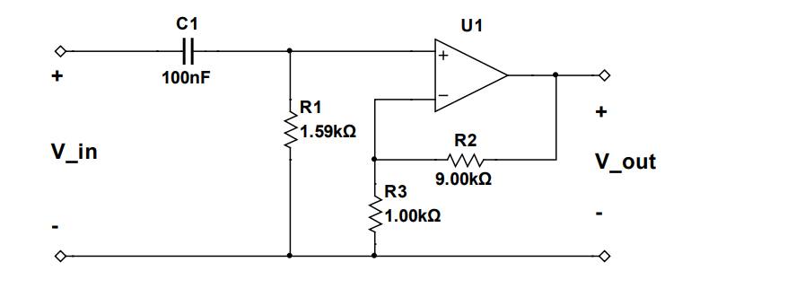
I have this circuit:

enter image description here

I am asked to show that the transfer functions of the circuit is:

enter image description here

I know that for non-inverting op-amps:

\$ Z_{in}=\infty \$

\$ Z_{out}=0 \$

\$ H(s)=\frac{V_{out}(s)}{V_{in}(s)} = \frac{Z_{1}(s)+Z_{2}(s)}{Z_{1}(s)} = \frac{Z_{2}(s)}{Z_{1}(s)} +1 \$

But if I set:

\$ Z_1 = 1.00\mathrm{~k\Omega} \$

\$ Z_2 = 9.00\mathrm{~k\Omega} \$

I just get:

\$ H(s)=\frac{V_{out}(s)}{V_{in}(s)} = \frac{Z_{1}(s)+Z_{2}(s)}{Z_{1}(s)} = \frac{9.00\mathrm{~k\Omega} + 1.00\mathrm{~k\Omega}}{1.00\mathrm{~k\Omega}} = 10.00\mathrm{~k\Omega} \$

which is not the same as:

enter image description here

What am I doing wrong here?

\$\endgroup\$
6
  • 1
    \$\begingroup\$ You forgot to include C1 and R1 effects. That makes all the difference. \$\endgroup\$
    – Andy aka
    Commented Apr 9, 2023 at 16:15
  • \$\begingroup\$ Hi @Andyaka won't they be zero in this case (because its an non-inverting om-amop)? and what is then Z1 and Z2 ? \$\endgroup\$ Commented Apr 9, 2023 at 16:22
  • 1
    \$\begingroup\$ Did you read my comment on your other question? \$\endgroup\$
    – Andy aka
    Commented Apr 9, 2023 at 16:23
  • \$\begingroup\$ No - but I just saw it. I will read the stackexchange codex ASAP \$\endgroup\$ Commented Apr 9, 2023 at 16:49
  • 2
    \$\begingroup\$ Aside from missing the effects of the capacitor, your H(s) units make no sense. It may seem like a small thing but if you get into more complex algebra one tiny error can cause a lot of wasted work. \$\endgroup\$ Commented Apr 9, 2023 at 18:34

2 Answers 2

7
\$\begingroup\$

You forgot to include the high-pass filter at the input. Solve for its transfer function, and then multiply it by 10, which is the gain you calculated for the op-amp transfer function.

EDIT: In one of your comments under your post you asked:

won't they be zero in this case (because its an non-inverting op-amp)? and what is then Z1 and Z2 ?

No, they won't. The only case where an impedance at that node doesn't make a difference is if it were a resistor inserted in series with the (+) input. Since it is a capacitor, you can imagine that it has an infinite at DC and becomes a short at high frequencies.

On the other hand, if there were no RC network at the (+) input of the op-amp, then you can assume its input impedance to be large at low-frequencies (~Mohms to Gohms even). However, now there is \$R_1\$ to ground. Therefore, your signal source sees an equivalent impedance of \$R_1\$ to ground approximately (it'll be \$R_1\$ in parallel with the input impedance of the Op-Amp itself), and this has an effect.

If \$R_1\$ were, on the other hand, a resistor in series with the (+) input, it'd be like adding \$R_1\$ plus the input impedance of the Op-Amp, which is already large, so now it'll be a bit larger; nothing significant changes for the input signal.

\$\endgroup\$
2
  • 1
    \$\begingroup\$ This is the better way to see it without letting a forest of math get in the way. Very simple. The math will follow, but "seeing meaning" is as important if not more-so. +1 \$\endgroup\$ Commented Apr 10, 2023 at 0:54
  • 1
    \$\begingroup\$ @periblepsis thanks for your kind words :) \$\endgroup\$
    – Designalog
    Commented Apr 10, 2023 at 8:18
5
\$\begingroup\$

Well, notice that in an ideal opamp we know that:

$$\text{V}_+=\text{V}_-\tag1$$

Using the voltage divider formula, we see that:

$$\text{V}_+=\frac{\text{R}_1}{\text{R}_1+\frac{1}{\text{sC}}}\cdot\text{V}_\text{i}\tag2$$

And:

$$\text{V}_-=\frac{\text{R}_3}{\text{R}_3+\text{R}_2}\cdot\text{V}_\text{o}\tag3$$

So:

$$\frac{\text{R}_1}{\text{R}_1+\frac{1}{\text{sC}}}\cdot\text{V}_\text{i}=\frac{\text{R}_3}{\text{R}_3+\text{R}_2}\cdot\text{V}_\text{o}\tag4$$

Which gives:

$$\mathscr{H}\left(\text{s}\right):=\frac{\text{V}_\text{o}}{\text{V}_\text{i}}=\displaystyle\frac{\frac{\text{R}_1}{\text{R}_1+\frac{1}{\text{sC}}}}{\frac{\text{R}_3}{\text{R}_3+\text{R}_2}}=\frac{\text{R}_1}{\text{R}_1+\frac{1}{\text{sC}}}\cdot\frac{\text{R}_3+\text{R}_2}{\text{R}_3}=\frac{\text{sCR}_1}{1+\text{sCR}_1}\cdot\left(1+\frac{\text{R}_2}{\text{R}_3}\right)\tag5$$

So, for the amplitude we get:

\begin{equation} \begin{split} \left|\underline{\mathscr{H}}\left(\text{j}\omega\right)\right|&=\left|\frac{\text{j}\omega\text{CR}_1}{1+\text{j}\omega\text{CR}_1}\cdot\left(1+\frac{\text{R}_2}{\text{R}_3}\right)\right|\\ \\ &=\frac{\left|\text{j}\omega\text{CR}_1\right|}{\left|1+\text{j}\omega\text{CR}_1\right|}\cdot\left|1+\frac{\text{R}_2}{\text{R}_3}\right|\\ \\ &=\frac{\omega\text{CR}_1}{\left|1+\text{j}\omega\text{CR}_1\right|}\cdot\left(1+\frac{\text{R}_2}{\text{R}_3}\right)\\ \\ &=\frac{\omega\text{CR}_1}{\sqrt{1^2+\left(\omega\text{CR}_1\right)^2}}\cdot\left(1+\frac{\text{R}_2}{\text{R}_3}\right)\\ \\ &=\frac{\omega\text{CR}_1}{\sqrt{1+\left(\omega\text{CR}_1\right)^2}}\cdot\left(1+\frac{\text{R}_2}{\text{R}_3}\right) \end{split}\tag6 \end{equation}

And for the argument:

\begin{equation} \begin{split} \arg\left(\underline{\mathscr{H}}\left(\text{j}\omega\right)\right)&=\arg\left(\frac{\text{j}\omega\text{CR}_1}{1+\text{j}\omega\text{CR}_1}\cdot\left(1+\frac{\text{R}_2}{\text{R}_3}\right)\right)\\ \\ &=\arg\left(\frac{\text{j}\omega\text{CR}_1}{1+\text{j}\omega\text{CR}_1}\right)+\arg\left(1+\frac{\text{R}_2}{\text{R}_3}\right)\\ \\ &=\arg\left(\text{j}\omega\text{CR}_1\right)-\arg\left(1+\text{j}\omega\text{CR}_1\right)+\arg\left(1+\frac{\text{R}_2}{\text{R}_3}\right)\\ \\ &=\frac{\pi}{2}-\arg\left(1+\text{j}\omega\text{CR}_1\right)+0\\ \\ &=\frac{\pi}{2}-\arctan\left(\frac{\omega\text{CR}_1}{1}\right)\\ \\ &=\frac{\pi}{2}-\arctan\left(\omega\text{CR}_1\right) \end{split}\tag7 \end{equation}

\$\endgroup\$

Your Answer

By clicking “Post Your Answer”, you agree to our terms of service and acknowledge you have read our privacy policy.

Not the answer you're looking for? Browse other questions tagged or ask your own question.