2
\$\begingroup\$

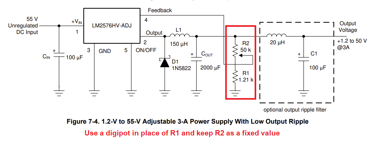
I am trying to design a buck converter using an LM2576HV (Vref: 1.23 V) and a digital potentiometer (input: 48 V, output: 0 to 48 V, Imax= 3 A).

The digital potentiometer with the highest supply voltage I could find works with 36 V. So I can only get 1.23-36 V at the output of the buck converter.

I am thinking of using a linear regulator like a TPS7A4101 that converts 48 V to 36 V to be able to supply the potentiometer, then using an op-amp to be able to increase the digital potentiometer output from 36 to 48 V. In this way, the output will be 1.65-48 V.

Would this be the right approach or should I go a different way? I have doubts about whether I can get enough current from the op-amp output.

Also I can't get 0 V at the output because of the reference voltage of the LM2576HV. How can I reduce the minimum voltage at the output from 1.65 to 0 V?

\$\endgroup\$
3
  • 6
    \$\begingroup\$ Welcome! Schematic please. \$\endgroup\$
    – winny
    Commented Aug 5, 2022 at 10:12
  • 2
    \$\begingroup\$ Datasheet for digital potentiometer please. You seem to be making the design difficult by your potentiometer choice. What is your goal? Is everything else in your system analog? \$\endgroup\$
    – Mattman944
    Commented Aug 5, 2022 at 10:16
  • \$\begingroup\$ Please provide a schematic of the converter circuit before requesting to reopen. \$\endgroup\$
    – Voltage Spike
    Commented Jul 6, 2023 at 15:59

3 Answers 3

6
\$\begingroup\$

You don’t need a high voltage device to control the regulator. You only need to alter the current going to its feedback node, which is at 1.23V.

Maxim Integrated makes a family of current source/sink DACs that are ideal for this. They use I2C control to set the current in or out of the DAC, which then is used to inject current to the voltage divider at the feedback node. This yields a digital control over the output voltage.

Example: DS4432 (link: https://www.maximintegrated.com/en/products/analog/data-converters/digital-to-analog-converters/DS4432.html)

Since the DAC can source as well as sink, it’s even possible to set output voltages below Vref. That’s not possible using a digipot.

There are other problems with a digipot approach. Using one to control just the lower resistor, while avoiding the high voltage problem, has a 1/R relationship to voltage. On the other hand controlling just the upper resistor does have a linear R-to-Vout relationship, but exposes the digipot to full output voltage (the very issue you’re facing) and also has some influence over the feedback loop. Finally, just using the digipot wiper to FB has the same voltage exposure problem, and also shorts FB to ground (or close to it) at one extreme, making the regulator run open-loop.

The current DAC approach, properly applied, has none of these issues. You have control over the span of the adjustment by selecting the right divider resistors and current DAC max output.

Digipot or DAC, you will need to consider startup behavior. The Maxim DAC makes this a bit more manageable as it powers up sinking/sourcing no current. This makes your default voltage just the voltage divider setting, as Vout = Vref*(1 + R2/R1).

\$\endgroup\$
3
\$\begingroup\$

The LM2576HV regulates when the feedback signal to pin 4 is around 1.23 volts so, use the digipot from FB down to ground and have an upper resistor to the output voltage of suitable value: -

enter image description here

This will allow you to get up to whatever voltage you need but, it won't allow you to turn off the output below 1.23 volts. However, you can fudge this by injecting a current into the FB node.

One thing you have to watch for is the increased capacitance on the FB node that the digipot brings and you'll probably need to compensate for this with a capacitor across your upper resistor.

\$\endgroup\$
2
\$\begingroup\$

Wire your converter for 1.2V output, with the output connected to the feedback pin via a resistor of suitable value R.

Then, use a current source of value I to pull a current from the feedback node.

This will shift the output voltage by R.I.

You don't need a digipot.

This is much simpler, and the loop gain and transient response will remain the same no matter what the output voltage setting is.

\$\endgroup\$

Not the answer you're looking for? Browse other questions tagged or ask your own question.