0
\$\begingroup\$

I have an application where I need to be able to drive an LED without a resistor. Adding a resistor is not an option. I then must be able to blink the LED on or off by shunting to ground.

LED Specs: Vf = 2.2V, I (nominal) = 20mA

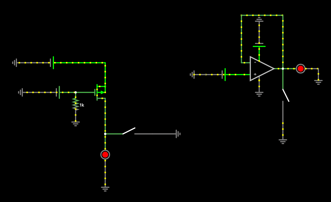
Would either of these configurations be viable? For the op amp, I would look for a component with an output short circuit current that's within the range of what an LED would need. For the MOSFET, I would need something in saturation at 5V, that can then have the current lowered by adjusting Vgs.

Is there a better solution or IC on the market that does this already? An LED driver of some kind? The only other condition is that the driver must drive the anode side of the LED.

enter image description here simulation

Engineering reasons for doing this:

If an LED was accidentally wired without a resistor it will not get destroyed. That's basically it. Convenience. The end user can operate an LED with or without the resistor. Optional.

Another example of why you would do this. Lets say you want to detect whether an enable pin is held to ground or not, without pulling current away from the pull-up.
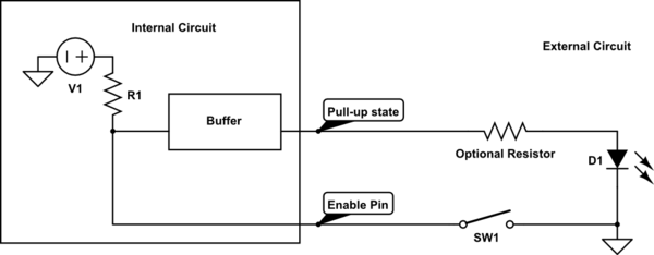
schematic

simulate this circuit – Schematic created using CircuitLab

\$\endgroup\$
17
  • \$\begingroup\$ What is the range? With fixed input and Vf, all you need is a fixed resistor. Is on-off ok or do you need dimming? If yes, analog or PWM? \$\endgroup\$
    – winny
    Commented Aug 16, 2023 at 15:45
  • 6
    \$\begingroup\$ This feels like a gap in understanding. You're willing to add an IC, but not a single common discrete resistor. Please enlighten us with the totality of your circuit and limitations. I'm concerned that this is an XY situation. en.wikipedia.org/wiki/XY_problem \$\endgroup\$ Commented Aug 16, 2023 at 16:06
  • 3
    \$\begingroup\$ "The LED is located somewhere outside of the device in such a way that a resistor cannot be added. It cannot be added inside of the device either..." But yet an IC can be added? Why do you surmise that adding an IC easier/less complicated than using any other component type, especially discrete parts? I'm not challenging your position; I just don't understand it. \$\endgroup\$ Commented Aug 16, 2023 at 18:37
  • 2
    \$\begingroup\$ As others have said why not just use a resistor? For example replace the MOSFET in your first diagram with a resistor, that would work (depending upon your supply voltage). Also please put reference designators in schematics so we can refer to components unambiguously. \$\endgroup\$ Commented Aug 16, 2023 at 23:58
  • 1
    \$\begingroup\$ If you use a current source, you can power the LEDs without resistor. That's what many LED drivers do. \$\endgroup\$
    – Velvet
    Commented Aug 17, 2023 at 10:49

5 Answers 5

2
\$\begingroup\$

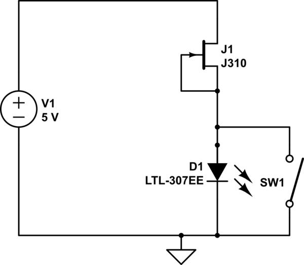
A N-channel JFET like BF256 can do this job without any resistor, connecting gate to source (Vgs=0). It is a RF transistor, low power, and there several types. enter image description here

schematic

simulate this circuit – Schematic created using CircuitLab
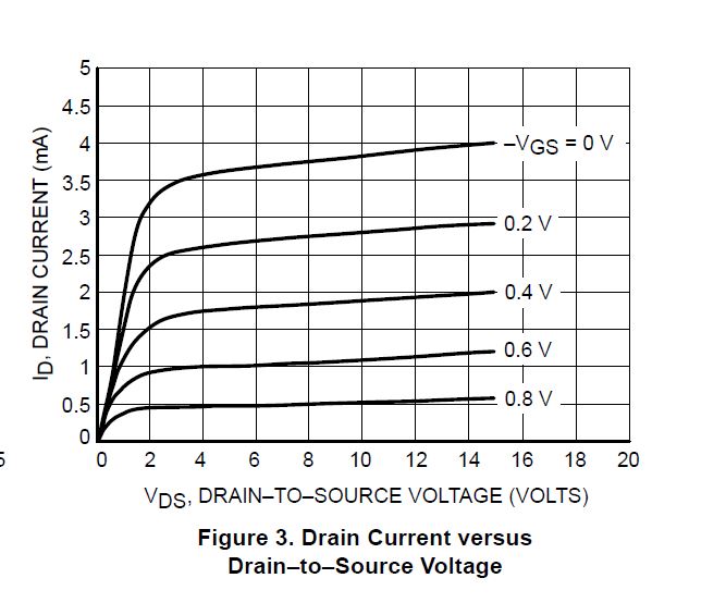
See the current curves for BF256A, they are not completely flat, but I think it is acceptable for a LED from Vds > 3 V.

enter image description here

\$\endgroup\$
2
  • \$\begingroup\$ Any particular reason to use a JFET vs a MOSFET? Been a while since i’ve worked with JFET’s \$\endgroup\$
    – BobaJFET
    Commented Aug 17, 2023 at 13:10
  • 1
    \$\begingroup\$ Not easy to find a depletion mode MOSFET, with some mA saturation at Vgs=0 . With some amount of Vgs you can get saturation more easy, but then you need a resistor to get it. \$\endgroup\$
    – Bravale
    Commented Aug 17, 2023 at 15:46
3
\$\begingroup\$

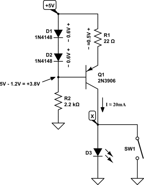
Any current source will do, such as this simple design:

schematic

simulate this circuit – Schematic created using CircuitLab

You can safely open and close SW1, and current \$I\$ will remain about 20mA. The potential \$V_X\$ at node X will adopt whatever value is necessary to pass 20mA through whatever load is below it, be that an LED, a resistor or a short circuit.

Change R1 to set \$I\$ to whatever (reasonable) current you desire:

$$ R_1 \approx \frac{0.5V}{I} $$


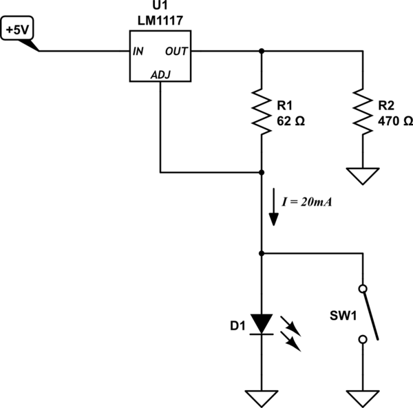
Alternatively, use a low dropout linear voltage regulator, like the LM1117:

schematic

simulate this circuit

R2 is only necessary for currents under about 5mA, necessary to obtain the necessary minimum load current for the LM1117 to regulate properly. For \$I>5mA\$ you may omit R2. Current \$I\$ is determined by R1:

$$ R_1 = \frac{1.25V}{I} $$


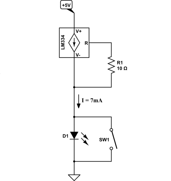
Then there's the good old LM334, designed specifically for this purpose. I include it for completeness, but I admit you can only get 10mA out of this, so it might not be suitable for your needs:

schematic

simulate this circuit

$$ R_1 = \frac{0.07}{I} $$

This is somewhat temperature dependent (one of the uses of the LM334 is temperature sensing), but you'll probably not notice much (if any) LED brightness change over typical room temperature variations. On page 8 of the datasheet you can find modifications to cancel this dependency.

\$\endgroup\$
1
\$\begingroup\$

You could use a transconductance amp as the current source. MAX426 can supply 20ma, and the output current is proportional to the input voltage. You could also use it as a sink, with the input controlled by your driver.

\$\endgroup\$
1
  • \$\begingroup\$ I think max426 is obsolete. \$\endgroup\$
    – BobaJFET
    Commented Aug 17, 2023 at 10:45
0
\$\begingroup\$

Adding a resistor is not an option

Yes, it is.

I understand that adding a resistor out at the LED is not an option, because of wiring, physical access, etc. But if you can add a 1- of 2-transistor constant current source, of a FET driver, or an opamp, or whatever at the driving point, then I don't understand why you cannot skip all of those relatively complex solutions in favor or a simple resistor at the same location.

For a 2 V LED operating at 20 mA from a 5 V source, the ideal resistor value is 150 ohms. Power dissipation in the resistor will be 60 mW, so anything rated at or above 100 mW will work.

If the voltage source for the LED is variable, or unknown within a certain range, then a case can be made for a constant-current driver. You do not explicitly state a source voltage, but one statement implies that it is a fixed 5 V source. If so, then a fixed resistor should work nicely.

\$\endgroup\$
1
  • \$\begingroup\$ I added some reasons why. Please take a look. \$\endgroup\$
    – BobaJFET
    Commented Aug 18, 2023 at 16:57
0
\$\begingroup\$

XY problem. If you can add an active current limiter, you can certainly add a resistor (you’d need several resistors for any sort of a discrete constant-current circuit anyway.)

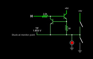
Probably the most economical is a discrete 2-transistor limiter built from two NPN devices, hacked in a way that allows logic control.

Example (simulate it here):

enter image description here

And I get what you're looking for - the ability to check for stuck-at states, as might apply for functional safety; the current limiter will let you do that.

In a FuSa scenario, your host would monitor the voltage during 'on' and 'off' to detect one of the stuck-at or open-circuit failures. Your host would also also know if a resistor were inserted since there would be an abnormally high voltage at the current source when the driver is 'on'.

Skipping the current limiter is an option too: just use a local load resistor. Since you know that resistance, and what the LED forward drop should be, you'd be able to see not only stuck-at or open-circuit faults, but if an additional resistor were inserted.

\$\endgroup\$
1
  • \$\begingroup\$ Please read the two examples I added. \$\endgroup\$
    – BobaJFET
    Commented Aug 18, 2023 at 17:07

Your Answer

By clicking “Post Your Answer”, you agree to our terms of service and acknowledge you have read our privacy policy.

Not the answer you're looking for? Browse other questions tagged or ask your own question.