12
\$\begingroup\$

I'm connecting a Sparkfun Artemis Redboard to a SCD41 CO2 sensor via a TCA9548A I2C multiplexer. There are 6 sensors connected to the multiplexer with long cables, so ideally the solution complexity won't scale with the number of sensors. This is outdoors in a fairly low-noise setting.

I know that this is a tradeoff between pullup resistance, clock frequency, and cable capacitance.

The internal pullup resistance for the Artemis is 1.5 kΩ, and given the 3 mA sink current requirement and 3.3 V voltage, I don't think there's much room to reduce pullup resistance.

Clock frequency seems promising. Is there any downside--besides time to complete a communication--for turning it down from 100 kHz to, say, 1 kHz? Which would presumably enable a cable with 100x the length to be used?

Finally, CAT5 seems to be the standard low-capacitance cable I'm finding (~50 pF/m). Are there other good options I should consider? How important is shielding compared to capacitance?

I'm aware that this is not what I2C is designed for and the "correct" answer is to use a different protocol.

\$\endgroup\$
14
  • 1
    \$\begingroup\$ Cat5 at 10 metres will probably work with no changes. However interference will be the big problem. Shielding will only do so much and i2c will frequently lock up. There’s also lightning protection to consider. You know it’s a bad idea. Go wireless? \$\endgroup\$
    – Kartman
    Commented Aug 22, 2023 at 22:19
  • 1
    \$\begingroup\$ I appreciate the response. By interference, do you mean from ambient EM noise? Do you still consider that an issue in a remote area, far from buildings and power lines? Basically, nothing here except a weather station, and the CO2 sensing system itself. I want to stick to I2C because we no longer have time for evaluating and integrating new electronics. \$\endgroup\$
    – Vulcan
    Commented Aug 22, 2023 at 23:28
  • 3
    \$\begingroup\$ CAT5 is a differential cable, and I2C is not designed for differential signalling. Can you clarify how you plan to drive the cable? A schematic might help. \$\endgroup\$
    – The Photon
    Commented Aug 23, 2023 at 1:05
  • 3
    \$\begingroup\$ @Vulcan, If you don't use half of a pair, you won't get 50 pF/m, you'll get some uncontrolled mess. \$\endgroup\$
    – The Photon
    Commented Aug 23, 2023 at 1:28
  • 7
    \$\begingroup\$ "How should I optimize I2C communication over a 10 to 25 meter cable?" You shouldn't. Use a suitable technology instead, CAN bus for example. \$\endgroup\$
    – Lundin
    Commented Aug 23, 2023 at 7:46

6 Answers 6

29
\$\begingroup\$

Don't.

First, shielded cable is required. I2C is a two-line, single-ended interface. It has a high impedance, and a low logic threshold voltage, so it is very susceptible to ambient noise in both the high and low states. Finally, it's edge-triggered (minus a small spike-filtering period of 50ns or so), ensuring that any line corruption also causes data corruption, and at the very least an error-retry or repeat-transmission or write-verify operation will be desirable, if possible at all.

Second, cable length is limited by total bus capacitance, which will be way out of spec here. Stock I2C is just straight out.

There is differential I2C, using converters; this resembles RS-485 or CANbus in terms of signaling, with a 3.3V (or whatever) differential signaling and more consistently low impedance (terminated 100 ohm lines). This tolerates more line length thanks to the resistance swamping cable capacitance, but it only marginally solves the noise problem: instead of a ~0.5V noise margin, it's roughly the supply (~5V).

(I've heard some controversy over this "theory", of what the limiting range of differential I2C is. Datasheets don't specify input common mode range, but input voltage range specs suggest clamping diodes, indicating a hard limit at the supply voltage, even if the input differential detection range extended beyond the supplies. I've yet to see a contradiction to this -- if you have such information, please add it in the comments, I'd love to know more about these devices!)

(There is also the temptation to believe "it says differential, it must be differential!", which I think is all too common, and just a result of not knowing better. We even see symptom of this in the PCA9615 datasheet itself. My counter to this: "how differential?" Any device in existence has some CMRR, and CM limit, whether that's the input range or supply voltage, somewhat beyond (e.g. RS-422's -7/+12V range even for 3.3V devices); or even if it's fully isolated -- Ethernet for example still only has a 1.5kV rating, and much less at high frequencies due to the ESD capacitor.)

In any case, I would expect differential I2C to be marginal in a commercial setting, i.e. 3V conducted, 3V/m radiated immunity. It should be fine at 1V or so, but may encounter errors beyond. Some filtering (CMCs are applicable here) may be able to extend it to 10V.

I would strongly encourage using shielded differential pairs (connect shield to circuit ground at both ends) to avoid the above questionable range; and, with good quality shields (metallic connectors, enclosures, etc.), you can probably get 50V+ of immunity this way. Kind of overkill if you just needed a few more volts of immunity, but sometimes that happens, too.

The above also covers the use of CAT-5: preferably, don't; or, use shielded twisted pair (STP) instead.

Shielding also vastly improves ESD immunity, enough that the system may remain operational under such conditions; whereas without, it most likely causes data corruption, or a power cycle is required to reset it.

Note that typical devices do not offer much ESD immunity, so external clamp diodes are strongly encouraged.

As for range, check the specifications and supporting information / application notes of the differential interface you choose (e.g. PCA9615). Curiously, I don't see much of any recommendation offhand, but I see users claiming operation out to 30m or so.

Anyway, third: supply consumption. The SCD4x specifies peak supply consumption up to 205mA. Beware of cable resistance, and ensure adequate supply at maximum current consumption and maximum supported distance. If you have spare pairs (e.g. Cat 5), you can use them in parallel for supply, doubling the usable range due to resistance limit.

The datasheet doesn't specify duration of that current draw unfortunately, though comparing to the periodic mode specs, it may be on the order of 500ms. Possibly, a local bulk capacitor could be paired with the sensor to supply some of this charge, but quite a large value would be needed (10s, 100s mF?). Better: use an excess supply voltage (e.g. 6-12V) at the connector, and use a 5V LDO for each sensor and interface chip.

Finally: what is a preferred solution, then?

I would recommend asynchronous serial (UART) over RS-422, via local MCU. If the sensors don't need any input (other than startup, provided by the MCU), merely two pairs will suffice (power and SDO+/-), and UTP (unshielded twisted pair) will be suitable (which includes two-pair cable e.g. Cat 3 and other types). Otherwise, 3 or 4 pairs for power (1 or 2 in parallel), SDO+/- and SDI+/-.

UART communications are not restricted by delay in any way (at least, not in and of themselves; typical protocols are extremely relaxed about timing), allowing up to the full ~km limits of RS-422 if you really needed it (of course, a local supply, or a more aggressive remote-power solution like say 48V plus a converter, will be needed then). Baud rate can also be quite high even over such distances (and to the point, higher than dI2C's limit), if that should be valuable. For this kind of sensor of course, quite low baud could be selected, gaining further EMC immunity by filtering lower.

And yes, this is a bother. That's more MCUs you need to buy, and place, and program. They only need to be programmed with one thing, once, of course (assuming you make the sensors either identical, or sufficiently general that they are compatible over whatever overall protocol solution you've employed), and low-performance MCUs can be quite cheap (a tinyAVR, or PIC, or STM32F0, or... would be more than sufficient).

(You may also want an additional MCU to coordinate the hub / router as well. Or perhaps choose a different topology: using RS-485 for example, with a suitable addressing or priority system, a single pair can be used for bidirectional communication over a common bus of devices all in parallel. Even better: use CANbus proper!)

Final note: if cross-wiring might be a concern, don't use 8P8C connectors that might get confused for Ethernet. Pick something else. Even just, various kinds of headers, will be acceptable for RS-422 (with suitable filtering in place to account for the unshielded length near the connector(s), and preferably with the shield connected through multiple pins across the header), or automotive or circular types may be attractive for compactness and environmental immunity (IP6x ratings, say).

Additional reading: I2C differential network architecture using PCA9615

\$\endgroup\$
10
  • 12
    \$\begingroup\$ "Don't" is the correct answer. Since this is an engineering site we do have an obligation to call out bad engineering. I'd personally always pick CAN over RS-422 given the choice, but either would work here. The learning curve for CAN might be a bit longer but it is more flexible and rugged overall, particularly when you need more than just point-to-point. \$\endgroup\$
    – Lundin
    Commented Aug 23, 2023 at 7:52
  • 4
    \$\begingroup\$ And to be clear -- I am speaking from my own experience, in which I haven't worked with a whole CAN thing top to bottom, but I've certainly used UARTs and RS-422 and such a solution is foreseeably tractable to me, so that's what I would do. Others may choose different combinations, or protocols, and that's fine, too. (I'd also be half-tempted to use Modbus over RS-485, which I have implemented before; assuming the sensors can be programmed with individual addresses of course.) \$\endgroup\$ Commented Aug 23, 2023 at 8:31
  • 4
    \$\begingroup\$ The various RS422/RS485 technologies are burdensome and quite outdated technologies. Things like Profibus or Modbus were always painful to work with (not to mention custom, home-brewed protocols), and there's a lot of issues with UART in itself. CAN is actually much smoother to work with once one is past the learning curve. The general trend I've been seeing in automation/traditional industry over the last 10+ years is that UART-based buses are getting phased out in favour of CAN. And the automotive industry always used CAN to begin with, since the 1990s. \$\endgroup\$
    – Lundin
    Commented Aug 23, 2023 at 9:04
  • 4
    \$\begingroup\$ @Lundin: Although some data encodings may have some advantage over the "UART-style" encodings that write a maximum of one byte every ten bit times, the only downside I see with UART-style communication for most tasks involving speeds below a million bits per second is is a need for a receiver to have a clock that can start timing received data immediately and even that may be mitigated by having packets start with multiple FF bytes, but specifying that any number of FF bytes preceding a packet will have no effect. \$\endgroup\$
    – supercat
    Commented Aug 23, 2023 at 16:56
  • 1
    \$\begingroup\$ @Lundin: In many cases, packet collisions may be prevented by having one device on the bus serve as the master, and saying that any other bus will only start speaking within a certain period of time of being addressed by the master. As a slight variation, in power-sensitive applications when using a signaling method where a quiescent bus would draw essentially zero power, the master may precede each communication with an "I'm about to speak" preamble, and other devices may send a "someone has something to say" pulse if they have something to say and the bus has been idle for awhile. \$\endgroup\$
    – supercat
    Commented Aug 24, 2023 at 14:39
13
\$\begingroup\$

I agree that a differential converter is probably necessary to make a long I2C bus work reliably. The reason why just lowering bitrate is not enough is not immediately obvious though, so I'll explain it below.

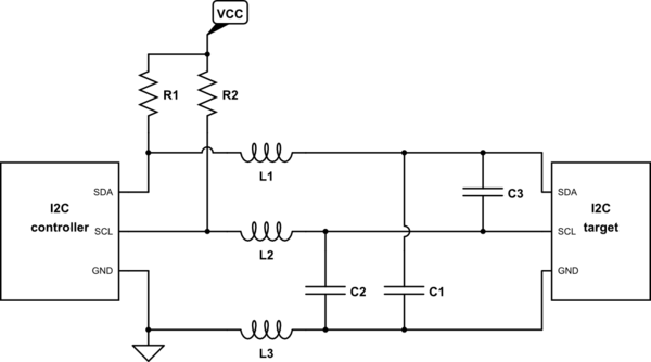
The equivalent circuit will be similar to what is below. L1-L3 represent the cable inductance and C1-C3 represent the cable capacitance. In reality they would be distributed along the cable.

schematic

simulate this circuit – Schematic created using CircuitLab

Bit rate limit

R1×C1 and R2×C2 determine the maximum bitrate of the I2C bus. Typically you can use pull-up resistor values down to 2 kΩ. With the approximated 1000 pF cable capacitance, that would give about 4 µs rise/fall times. This would be fine when at e.g. 10 kbps speed the bit times are 100 µs.

SDA-SCL capacitive coupling

The first actually difficult problem is C3 - the cable capacitance between SDA and SCL. When the target device pulls down SDA to send data, it will capacitively couple to the SCL wire. This will cause a glitch that makes the target think that the bit already ended.

For an unidirectional bus such as SPI, glitches can be reduced by adding a series resistor, which intentionally slows down the rise and fall times. The slower the voltage change, the smaller current flows through the capacitor. But for I2C, the series resistor would have to be small in comparison to the pull-up resistors R1 and R2. Hitting a good balance is not straightforward.

Individually shielded conductors can avoid C3 entirely, at the cost of increasing C1 and C2.

Cable inductance

Even if the C3 coupling capacitance is eliminated, the inductive coupling between cable inductances L1 and L2 can cause similar glitches. At I2C speeds, the inductive coupling is usually less of a concern than the capacitive one.

Recommendations

If you want to try this anyway, I would recommend:

  1. Select cable with individually shielded SDA and SCL wires if possible. If not, run them as separate pairs, each twisted with a GND wire.
  2. Add a small series resistor to SDA and SCL pins at each end - 100 ohms would be a typical value.
  3. Adding capacitors between SDA-GND and SCL-GND on the bus side of the series resistors can be used to further slow down the rise and fall times to reduce coupling glitches.
  4. Consider putting pull-up resistors R1 and R2 at the target side of the cable, to reduce effect of cable inductance. The controller isn't as sensitive to glitches because it uses internal clock instead of SCL line. Only works for single target per bus.
  5. Use I2C routines with robust recovery. Typically after a failed transfer, you would manually send multiple SCL clock pulses, followed by a STOP condition.
\$\endgroup\$
11
\$\begingroup\$

As you know the situation is far from what I2C is intended and quite difficult or challenging. But desiging with the best possible tricks may allow you to make it work but it depends on what is the expected reliability. Some best hardware practices combined with software tricks to handle stuck communication also allows recovery from many problems.

What most answers have said, it will be difficult and should not be done, but given the best practices and ideas even from the I2C specification, it might be possible to some extent.

I will not repeat most of the things said in existing answers, but I present some additional things and software tricks.

Even when I2C specification says there is a limit like 400pF of capacitance and some pull-up current, it also says a scenario which allows exceeding them to make the pull-up as strong as possible and to drop the clock frequency until the high and low levels are long enough after the rising and falling edges. Some I2C chips support higher current, with relaxed specs of 0.6V at 6mA, but this sensor is only rated for 0.66V at 3mA current which is weaker than usual, so even the sensor itself is outside I2C specs, but it does support up to 400 kHz which means the high and low periods can be shorter than with a 100 kHz device.

The sensor is also very difficult to power, it can draw up to 205mA current peaks at 3.3V and it must have voltage ripple below 30mV, so any supply voltage dropping due to cable resistance is bad. Optimally, the sensor should be run at 5V, and use local linear regulator, so there should be maybe 7 to 12V on the bus, depending on regulator.

The pull up on Sparkfun sensor board is 2.2k which is 2.27mA at 5V. While it is near the 3mA, the sensor is weak and it will output lower signal with less pull-up current. So 1.8mA allows it to go down to the I2C specs of 0.4V. And the pull-ups are on the sensor end, while they could be split between sensor and mux end.

Speaking of the mux, you will want to control the reset pin of the mux to recover from error and lockup states. Ideally each device on bus should have a reset pin to reset them, and failing that, a method to reset them by toggling their power supply. I guess you can skip that since you have the mux and have full control over it to make a bus reset in software, to recover each bus segment separately from any state to working state.

Using CAT5 should be fine, as long as you select the pairing properly. At least never pair up clock and data. For I2C it means you should pair clock and ground, and supply and data. Since you have extra pairs, maybe twist clock with ground, data with ground, and then the remaining could be two supply-ground pairs. I don't recommend having two supply wires as a pair.

Some series resistances between chips and cable may be a good idea to limit bus driving current and slew rate, to prevent fast edges ringing around and causing problems. Maybe even reserve space for adding small few pF filter caps on the chip or cable side of series resistors.

To have full control over bus reset sequence and the bus speed, software bit-banging the bus slowly might be an option, as depending on the MCU, their extra I2C features such as being always multimaster capable means they will at the first glitch determine that some other device is starting to communicate on bus and you have to check if that has happened to reset the I2C controller.

The differential I2C conversion modules can be a good idea between mux and sensor.

There are also all kinds of I2C bus buffers, repeaters and rise time accelerators for extending the bus or driving higher capacitances with faster edges. These may be useful too, but many (all?) of them have to be used very carefully so that they don't cause problems themselves, like many of them are not chainable so you can't have one on mux output port and another on the sensor input port. In a closed system you can select only compatible chips but if multiple vendors can make devices, there is a great chance that vendors make incompatible products even if the intention is good for adding I2C bus repeaters to allow better operation, but when another vendor adds another repeater, the products become incompatible on same bus.

\$\endgroup\$
7
\$\begingroup\$

There are line drivers like NXP's PCA9615 which convert I2C into a differential signal for transmission over twisted pair. There are also options to transmit power at a higher voltage, with local down conversion to make up for resistive losses.

If you are using sparkfun modules already, worth looking at their QwiicBus system which does both in a convenient form factor for daisy chaining QwiicBus. Claims to be good for 200ft, and I've used at 10m without issue.

\$\endgroup\$
4
\$\begingroup\$

25 meters seems to me ambitious for I2C. If it's a one of, you can try it in CAT cable, but I'd say it won't work reliably. Capacitance per feet is one of the metrics, but in the case of ethernet cable, this capacitance is measured between pairs and not between wires. In fact, your capacitance between two pair will be much greater.

If I was mandated to design that, I'll try to avoid it first! I don't see how 25 meters of any cable will work both for the I2C protocol nor for the powering of your device.

The issue you will have with such distance are:

  • Resistive loss in the transmission line (attenuation)
  • Capacitive and inductive loading (rigging and phase shifting)
  • Reflection
  • Propagation time issue (signaling)
  • EMI issues
  • Wave propagation phenomena

Each one of those will be hard to solve by their own. Increasing the amplitude of your signal will help. Lowering the frequency will help. Lowering the spectrum content will help­. Increasing the current will help. Both even with all those precautions in place, I don't think your system will be reliable.

Now, you haven't spoken about power supply, but it will be an issue too. 30AWG wire over 25 meters (back and forth, so 50m) is essentially 17ohm resistance. It might not seem significant but it is. With the amount of capacitance and inductance you will have, this 17ohm will make your power supply very unstable.

So what I would do. For starter, I would power with an higher voltage. I would probably go as high as I can without changing device class for electrical safety. Something around 50V. Then for signaling, I would use either high voltage level shifter or an other protocol that can be easily transduced in I2C. If I have noise issue, I would probably even try to make I2C to be differential. In any case, I think you need a custom protocol solution.

\$\endgroup\$
0
\$\begingroup\$

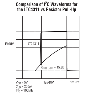
Use an active terminator. People have used the LTC4311 to send I2C through 100ft of cat5.

The terminator adds current to the bus when it detects a rising (and falling?) edge to make sharper edges. Here is a snip from the datasheet:

LTC4311 active terminator for i2c

\$\endgroup\$

Your Answer

By clicking “Post Your Answer”, you agree to our terms of service and acknowledge you have read our privacy policy.

Not the answer you're looking for? Browse other questions tagged or ask your own question.