0
\$\begingroup\$

This is my first time using an oscilloscope so please be gentle with me. I have Hantek 6022BE. The probe is calibrated right because I connected it to the pin on the oscilloscope with the square wave to calibrate it and I display the square wave correctly.

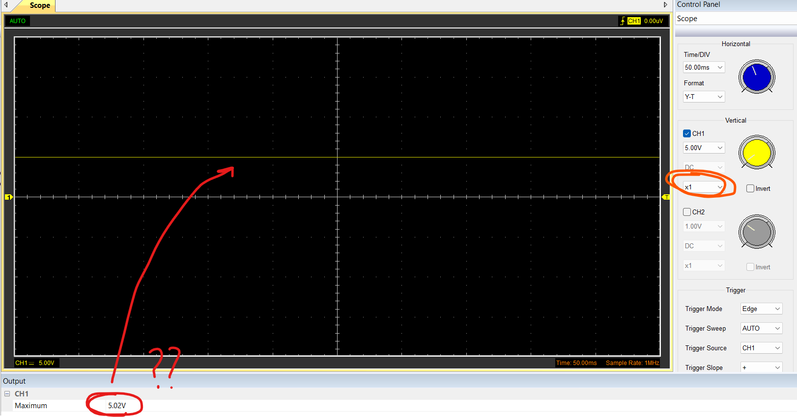
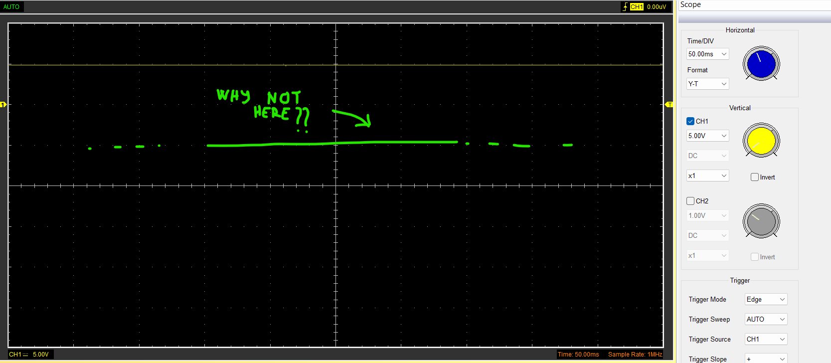
I connected the probe to the 5V supply on the stm32 and I see this: enter image description here 1) SOLVED If I set 5 V/div ... shouldn't I see the yellow line (of CH1) exactly horizontally coincident with the first division? From what I can see, it seems to be measuring 15V. Maybe I need to play with the trigger? I tried 2V/div as well, and the yellow line goes out of the display.
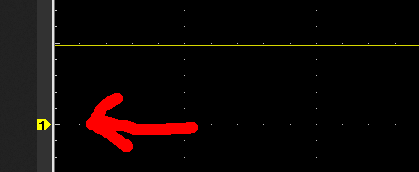
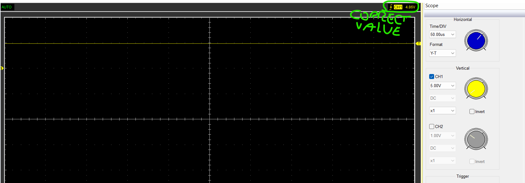
I tried moving the trigger exactly to the height of the yellow line: enter image description here
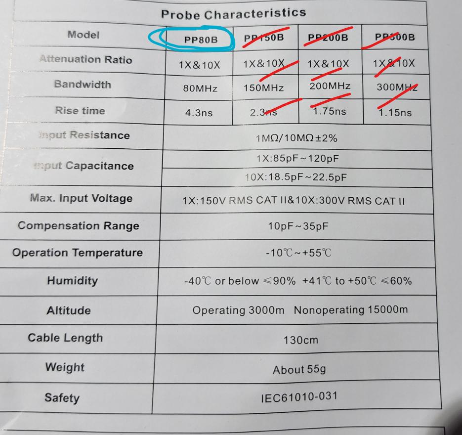
2) SOLVED I can't figure out what is the maximum voltage value that the oscilloscope can measure. In case you need, the probes are PB80B: enter image description here
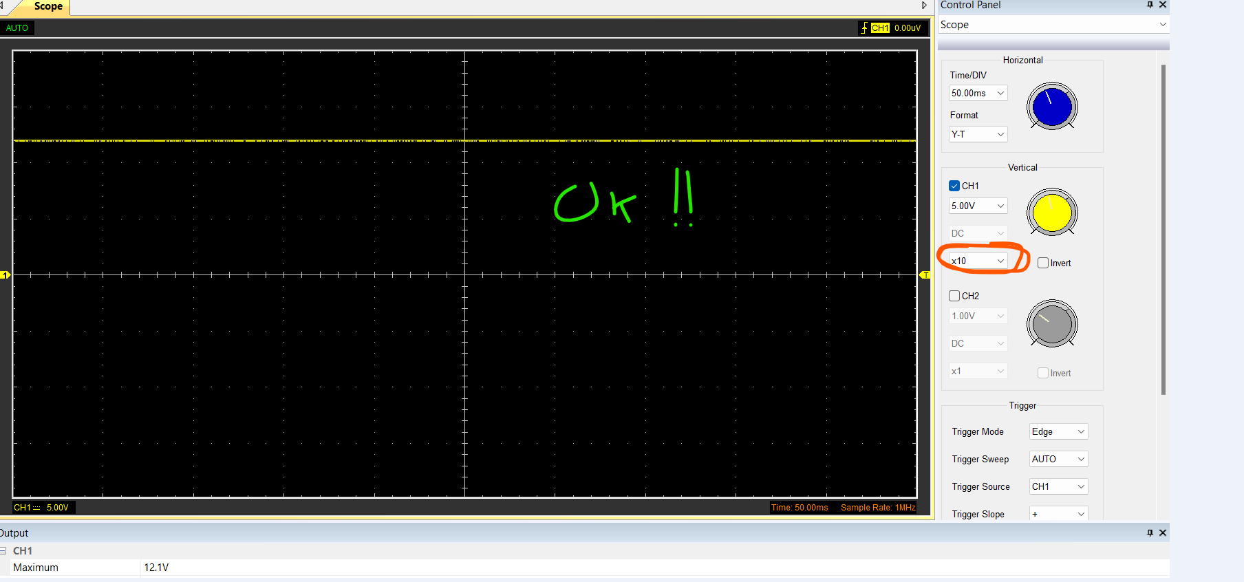
3) I tried connecting the probe to 12V DC, and depending on the probe (1X or 10X) I get these two graphs: enter image description here enter image description here Why do I see maximum 5V with the 1X probe?
\$\endgroup\$

3 Answers 3

2
\$\begingroup\$
  1. No because you have 0V offset of two divisions, so that's why 5V is at the third division. And trigger does not affect that, it is a separate concept.

  2. What oscilloscope can do is separate from probes. Your probes can do either 150V or 300V depending on which setting you use on the probe. We don't know if your scope is rated for more or less, so the limit is either set by the scope or the probe used.

\$\endgroup\$
1
\$\begingroup\$

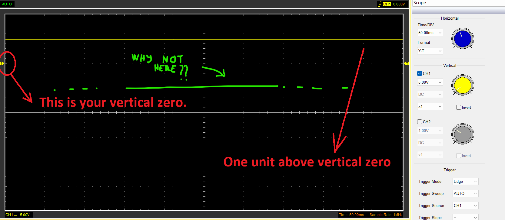
The zero of each trace is shown on the left.

enter image description here

In this case, your yellow trace is 4.88 V above the yellow marker for trace 1. All oscilloscopes have a knob to move the signal up and down visually. You can line it up on the crosshairs if you like. Usually there's a control per channel: it's probably the yellow virtual knob on the right of your image.

The maximum voltage for your probe is given as 150 VAC when set to x1, and 300 VAC when set to X10: the setting is usually a little switch on the probe. You usually have to tell the scope too, or the values will be 10X wrong.

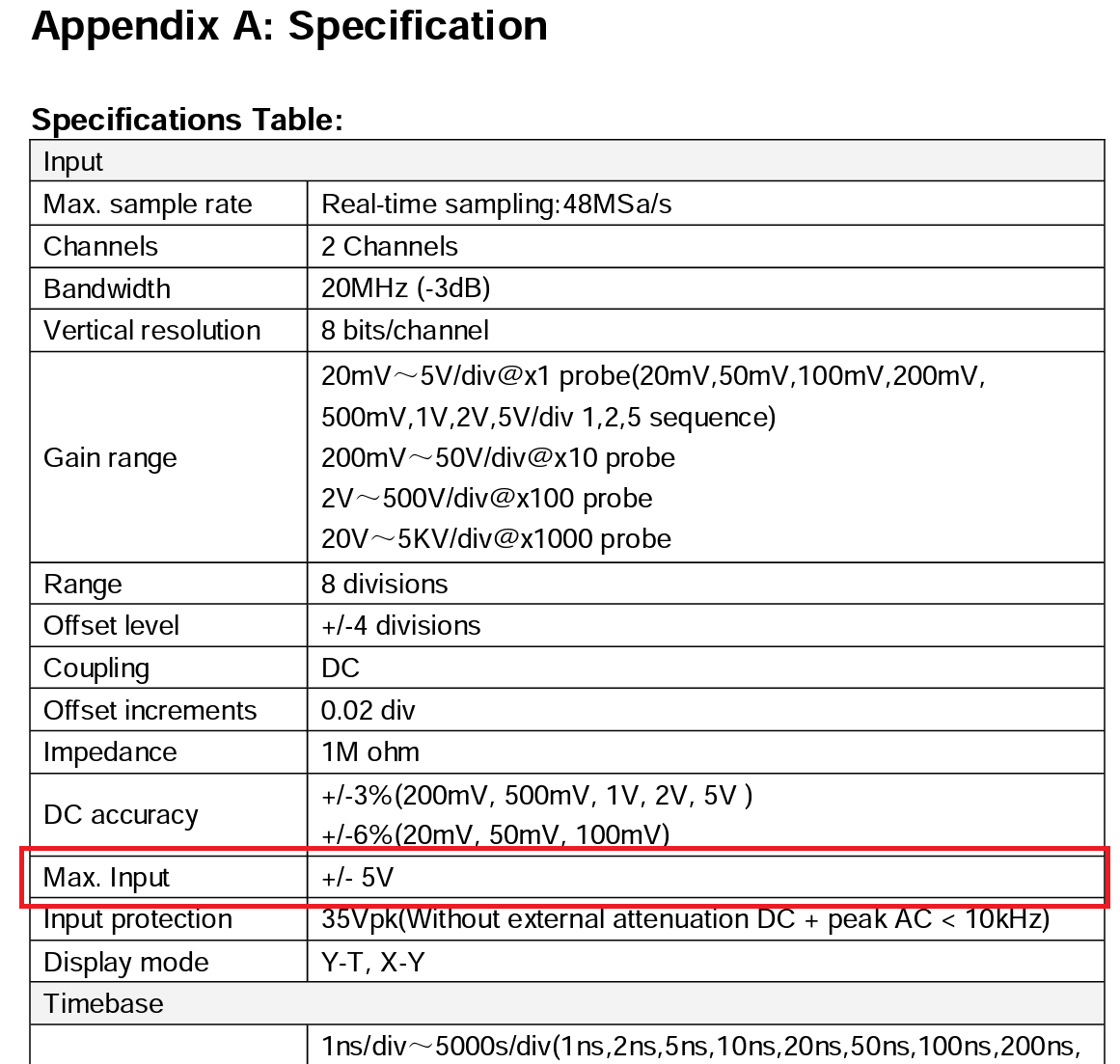
But note the maximum voltage for the oscilloscope will be elsewhere, and is a lot lower: 5V. (Hanktek Manual 6022BE)

This explains why you see 5V when you connect the probe to 12V: the scope has a maximum of 5V. if you're measuring above 5V you should use the problem in 10X to scale the voltage down.

This gives you an effective maximum voltage of 50 V on the 10X probe setting.

\$\endgroup\$
3
  • \$\begingroup\$ Thank you for the response! I edited the main post by adding question 3) \$\endgroup\$
    – KaleM
    Commented Oct 30, 2023 at 17:03
  • 1
    \$\begingroup\$ @kalem ... answered \$\endgroup\$
    – jonathanjo
    Commented Oct 30, 2023 at 17:22
  • \$\begingroup\$ Ops! Yes I read now in the datasheet that the max input is 5V. I will be more careful next time! Thank you very much \$\endgroup\$
    – KaleM
    Commented Oct 30, 2023 at 18:10
1
\$\begingroup\$
  1. The scope shows the correct value. You are confused because of the vertical position of the channel waveform:

enter image description here

If the scope or its control software allows (probably does) then set the vertical position to its default (probably the thick horizontal axis in the centre).

  1. Skipped (already marked as SOLVED by the OP)

  2. This is because of the input ratings of the scope itself. This is totally a separate rating from probes. See the section from the manual:

1)

The input signal will be clamped to 5V if it exceeds that level. Gained (10x, 100x, 1000x) probes are therefore useful as they allow you to measure even higher voltages.

\$\endgroup\$
3
  • \$\begingroup\$ Thank you for the response! I edited the main post by adding question 3) \$\endgroup\$
    – KaleM
    Commented Oct 30, 2023 at 17:03
  • \$\begingroup\$ @KaleM see the edit. \$\endgroup\$ Commented Oct 30, 2023 at 19:29
  • \$\begingroup\$ ±5 V on a 1 MΩ scope input? That sounds wrong, that's more what I'd expect for a 50 Ω input. 1 MΩ inputs on most scopes I've used are rated for somewhere in the 300 to 400 V range. \$\endgroup\$
    – Hearth
    Commented Oct 31, 2023 at 14:26

Your Answer

By clicking “Post Your Answer”, you agree to our terms of service and acknowledge you have read our privacy policy.

Not the answer you're looking for? Browse other questions tagged or ask your own question.