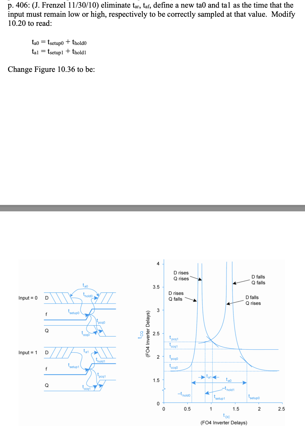
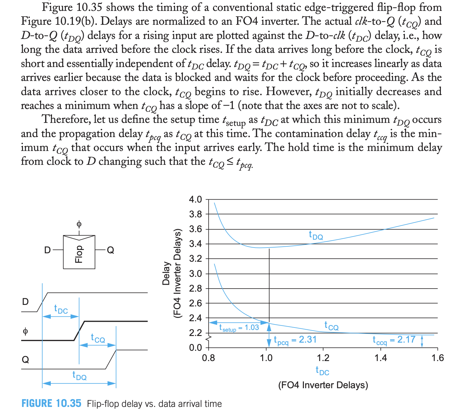
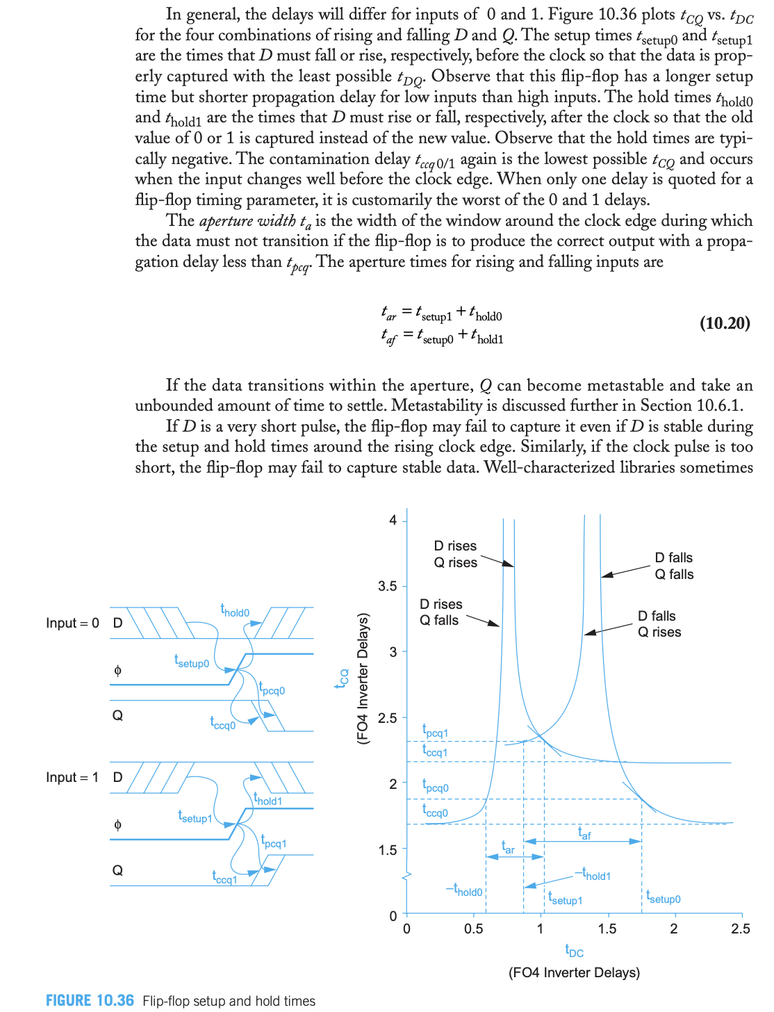
Consider the attached from Weste and Harris's (WH) CMOS VLSI Design. I follow all of the discussion and definitions except for the hold time definition.
Now I am familiar with the common/heuristic hold time definition which says something like "the time relative to the clock edge (measured positive past the clock edge) during which the data input must be stable for correct operation". There are of course analogous heuristic definitions for \$t_{setup}\$ and I do understand how these connect to the underlying definition given by WH. However, I can't follow for \$t_{hold}\$. Indeed, I don't even understand what they mean by "clock to D" here.
Edit:
In this edit I include the next page which may shed some light on my question.
My understanding/guess about the hold time is now the following. Let's focus on the given flip-flop intending to capture a \$D = 0\$ input. We examine first the "D falls Q falls" curve. We define \$t_{setup}\$ as the \$t_{DC}\$ at which the slope of the \$t_{CQ}(t_{DC})\$ curve equals -1. The corresponding \$t_{CQ}\$ value is called \$t_{pcq}\$ (the reason this definition makes sense is that, in our design, we will always arrange things such that tokens arrive before \$t_{setup}\$ so that, per the Figure, \$t_{pcq}\$ will indeed be an upper bound on \$t_{CQ}\$). We can also define \$t_{ccq}\$ as \$t_{CQ}\$ in the \$t_{DC} \to \infty \$ limit.
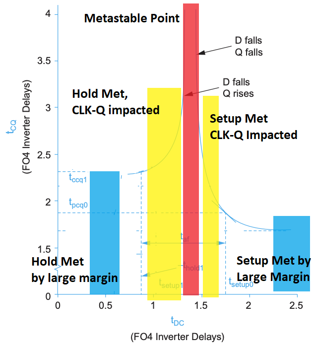
Now for hold time: We begin by examining the "D rises Q falls" curve. First of all, we notice that it has a vertical asymptote. We take this as implying that if D rises any earlier than this vertical asymptote then the flip-flop captures a 1 (rather than a 0) incorrectly. (An analogous comment applies to the vertical asymptote for "D falls Q falls".) Now among all of these times at which D can change to 1 and yet the flip-flop still correctly captures a 0, we see that the earlier this change happens the longer it takes for the flip-flop to capture that 0 (this presumably has to do with the inverters in the feedback loops of the flip-flop fighting each other, but we'll leave that aside). Among these \$t_{DC}\$, the hold time is defined as the negative of the maximum \$t_{DC}\$ such that \$t_{CQ} \leq t_{pcq}\$. This matches the definition given on the previous page by WH: "The hold time is the minimum delay from clock to D changing [i.e. \$-t_{DC}\$] such that the \$t_{CQ} \leq t_{pcq}\$ [and such that we get correct capture of the token].
My questions are as follows:
(1) Do you agree with my understanding of the hold time definition?
(2) Why is the added requirement of "such that the \$t_{CQ} \leq t_{pcq}\$" in the hold time definition necessary? Why not define the hold time as the vertical asymptote alluded to above? I think the answer is that our timing parameter definitions are such that, if we meet them, then we are guaranteed a maximum \$t_{CQ}\$ of \$t_{pcq}\$ whereas if we relaxed the hold time definition to be at that vertical asymptote then we might have huge \$t_{CQ}\$ delays. I would appreciate confirmation on this point.
(3) WH write "If D is a very short pulse. the flip-flop may fail to capture it even if D is stable during the setup and hold times around the rising clock edge." How can this be? Wasn't setup and hold time defined (among other things) to give a window during which we would get correct token capture if the D input is stable?
Edit 2:
As noted in a comment below, this version of the text has an error (a crucial one!) which is explained in an erratum by the authors below:


clock to D... it isclock to changingof D \$\endgroup\$