1
\$\begingroup\$

enter image description here

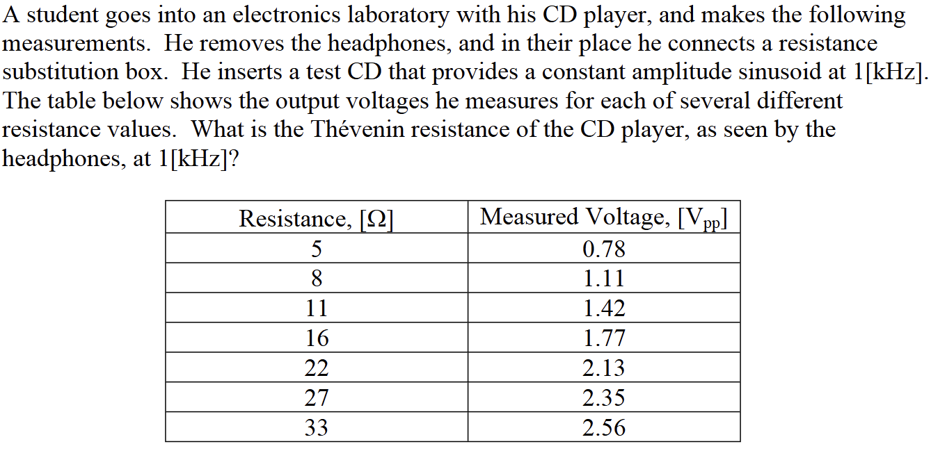
This review problem has been stumping me for days (very rusty). My initial approach was hooking up what I believe would be an AC source with \$V_p \times \cos(1000 \times 2\pi)\$ in series with an Rth and the changeable load resistances as the load.

Finding the Vp or Ip value has been the biggest roadblock for me. I thought I could find Ip by simply doing \$(V_\text{pp}/2)/(R_L)\$ for a random table selection, but this doesn't make sense since the amplitude is supposed to be constant. Only progress I've made was realize that the power factor is 1 and the circuit is in phase because of the pure resistive trait. Any tips or pointers as to how to approach this problem? Been having a tough time searching up similar uses of the thevenin theorem.

\$\endgroup\$
12
  • 1
    \$\begingroup\$ I like it. This is a great exercise! \$\endgroup\$
    – pipe
    Commented Aug 23 at 19:23
  • 1
    \$\begingroup\$ TheAttack, What do you know about the maximum power theorem? \$\endgroup\$ Commented Aug 23 at 19:39
  • 1
    \$\begingroup\$ Seems like you have a voltage divider with one unknown resistance, driven by a voltage source with an unknown value. But you have multiple data points for one resistance and the divider voltage. You only need two equations in two unknowns to find the answers. \$\endgroup\$
    – John D
    Commented Aug 23 at 20:50
  • 1
    \$\begingroup\$ @TheAttack55 I tried it and all the table values were consistent with my answers. So maybe try again? \$\endgroup\$
    – John D
    Commented Aug 23 at 22:52
  • 1
    \$\begingroup\$ @SteKulov My answer didn't give EXACT results, but 0.78, 1.126, 1.41, 1.786, 2.127, 2.347, and 2.56. Well within what you might expect from experimental error. You wouldn't expect the points to lie on a line since a voltage divider is R2/(R1+R2). \$\endgroup\$
    – John D
    Commented Aug 24 at 16:57

1 Answer 1

1
\$\begingroup\$

Draw the circuit diagram.

schematic

simulate this circuit – Schematic created using CircuitLab

This is one way of solving the problem for two unknowns (VT & RT):
Write the equation for Vo.
Rearrange the equation to solve for RT. This will give a function in the form of RT(Vo,RL) = some_equation
Since RT should be the same, choose two lines in the table and solve for VT.

With VT known (around 4.4 V), you can figure out RT (around 24 ohms). The numbers in the table don't give a clean answer (as in VT and RT are the exact same numbers) which may be part of the question to come up with an average value.

Where the power peaks up in the load (as suggested by @periblepsis) is another way of finding RT which in this case lies somewhere between 22 & 27 ohms.

\$\endgroup\$
2
  • \$\begingroup\$ Hmmm…some kind of averaging is what I initially thought of too. Then I thought it might be possible that whoever wrote this review problem might want an equivalent circuit for each adjacent pair of points. You think that’s possible too or a little too crazy? \$\endgroup\$
    – Ste Kulov
    Commented Aug 24 at 7:35
  • 1
    \$\begingroup\$ @SteKulov Anything is possible since we don't know what the chapter is about. Perhaps an exercise in a real world problem where errors in measurements can create a conundrum. \$\endgroup\$
    – qrk
    Commented Aug 24 at 16:13

Your Answer

By clicking “Post Your Answer”, you agree to our terms of service and acknowledge you have read our privacy policy.

Not the answer you're looking for? Browse other questions tagged or ask your own question.