0
\$\begingroup\$

I need a switch, but with a small twist. If it was operating on normal filtered DC I would know how to make one myself. But since it's for a car, I need help designing it for reliability and surge protection.

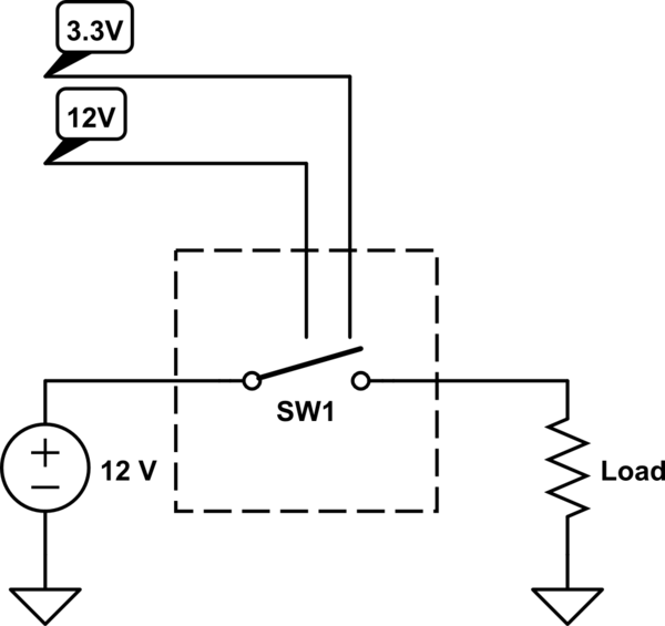
The most complicated thing about it will be the description, so please bear with me. Basically, what I need it is a switch with two independent control inputs. Input is active when there is voltage on it as described below, and inactive when there's no voltage (it'll be floating, not grounded). The switch should be shorted when either of the inputs is active, or both.

  • Control input #1 is from the car's power grid, which means 10 V to 15 V DC + noise and voltage spikes. They say the spikes can be up to 100 V, and can even have reverse polarity, and it's my main difficulty with this design - I don't know how to make the circuit work reliably in these circumstances.
  • Control input #2 is filtered 3.3V, so that one shouldn't be a big problem.
schematic

simulate this circuit – Schematic created using CircuitLab

What the circuit will be switching is also the car's power grid, so I don't know if I can use a MOSFET, for example - will it withstand a 100 V surge, which can have forward or reverse polarity? Current is 2 A with short peaks up to 3 A. The main +12 V input is always present, while the +12 V control input will appear and disappear.

It so happens that I also need to feed the 12 V control input that this circuit receives to a micro-controller's input, meaning I need to scale it down to +3.3 V or +5 V, and I need to remove the noise and voltage spikes in order to protect the MCU and detect the voltage reliably. So it will be beneficial if this switch will somehow filter and downscale the noisy input so that I can feed it to the MCU with no additional circuitry. Or at least filter out the noise so that I can connect the MCU's input via a MOSFET or an opto-isolator without the risk of this MOSFET / isolator being damaged by a voltage spike.

My original idea was 2 parallel MOSFETs with high enough gate-to-source voltage tolerance so that it can throughput 15 V while being driven by 3.3 V. And then I have to devise some kind of a filter for the MOSFET that's driven by the car's power grid, but I have no good ideas on how to do it both reliably and simply (with as few elements as possible). Maybe, a voltage regulator, like LM817? Will it withstand the voltage spikes? Will, like, a high-speed diode bridge for normalizing the polarity and an LC-filter do the trick? Also, I do not know if a MOSFET will withstand the car's voltage being passed into the source-to-drain channel, with its dual-polarity voltage spikes.

\$\endgroup\$
3
  • \$\begingroup\$ You are almost talking just about 100V spike, but where does it come from. Do you think that ECU in your car is designed for 100V spikes? The rest could be writen more readable, and what you want to do. Why both polaries, is the MCU on the same ground potential. \$\endgroup\$ Commented Jan 24, 2016 at 10:51
  • \$\begingroup\$ @MarkoBuršič: I am most certain the ECU is designed for at least 100V spikes. The reason I'm mostly talking about them is because if there was no such thing and the input was filtered, I'd just put 2 parallel MOSFETs and be done. As for where it comes from - I don't know the specific answer. Generally, it's said to come from the alternator's collector and from the ignition system. \$\endgroup\$ Commented Jan 24, 2016 at 10:52
  • \$\begingroup\$ @MarkoBuršič: I realize the question is a bit messy and hard to understand. That's the best I can do right now. If you can think of any way to improve the question, please do. I'm not sure I understand your question about the MCU, but all the circuitry in question has common ground. \$\endgroup\$ Commented Jan 24, 2016 at 10:53

2 Answers 2

1
\$\begingroup\$

schematic

simulate this circuit – Schematic created using CircuitLab

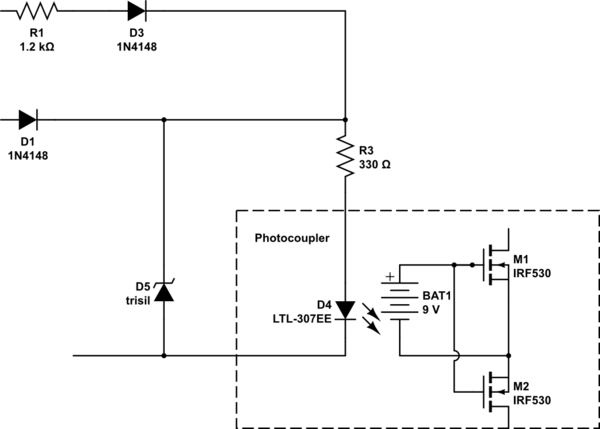
Something like that?

\$\endgroup\$
3
  • \$\begingroup\$ If I could understand what this thing does... A couple questions. 1. What are D1 and D3 for, and will they withstand the voltage spikes? Same question about D4, btw. 2. Won't D5 cause a fuse to blow (or blow itself) when activated? 3. Why 2 serial MOSFETs? \$\endgroup\$ Commented Jan 24, 2016 at 11:20
  • \$\begingroup\$ Yep, this is how can I draw in CircuitLab. D1 is the input for 3.3V signal, D3 is the input for 12V signal, both common ground. D5 is a transient suppressor diode that cuts the spike. The boxed element is photo relay, photo mosfet, photomos,...or wahtetever this new technology is called. The LED iluminates the photovoltaic array that produces drive volatge for the output mosfets in configuration ala AC switch. \$\endgroup\$ Commented Jan 24, 2016 at 11:28
  • \$\begingroup\$ I understand that. What I don't understand is: 1. D5 works by shorting voltage spikes to ground. Won't it blow a fuse by doing so? It is said the spikes can last as long as 400 ms: littelfuse.com/~/media/electronics_technical/application_notes/… And 2: will the D1 and D3 withstand a 100 V reverse polarity spike? From what I heard, pretty much all diodes are fragile when it comes to reverse voltage. \$\endgroup\$ Commented Jan 24, 2016 at 11:52
0
\$\begingroup\$

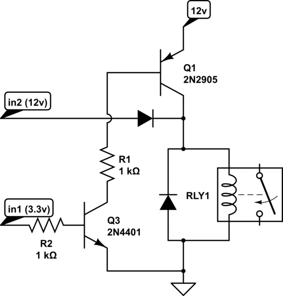
There's no such thing

Use a relay.

Use a bipolar transistor (or two) to interface your low voltage signal.

schematic

simulate this circuit – Schematic created using CircuitLab

\$\endgroup\$
4
  • \$\begingroup\$ No such thing as what? I would really prefer a solid-state solution. \$\endgroup\$ Commented Jan 24, 2016 at 11:05
  • \$\begingroup\$ mosfets are expensive and unreliable \$\endgroup\$ Commented Jan 24, 2016 at 11:06
  • \$\begingroup\$ I was just going to say relays are expensive! And they click. \$\endgroup\$ Commented Jan 24, 2016 at 11:07
  • \$\begingroup\$ solid state relays cost 10 times the price for a weaker part \$\endgroup\$ Commented Jan 24, 2016 at 11:11

Your Answer

By clicking “Post Your Answer”, you agree to our terms of service and acknowledge you have read our privacy policy.

Not the answer you're looking for? Browse other questions tagged or ask your own question.