0
\$\begingroup\$

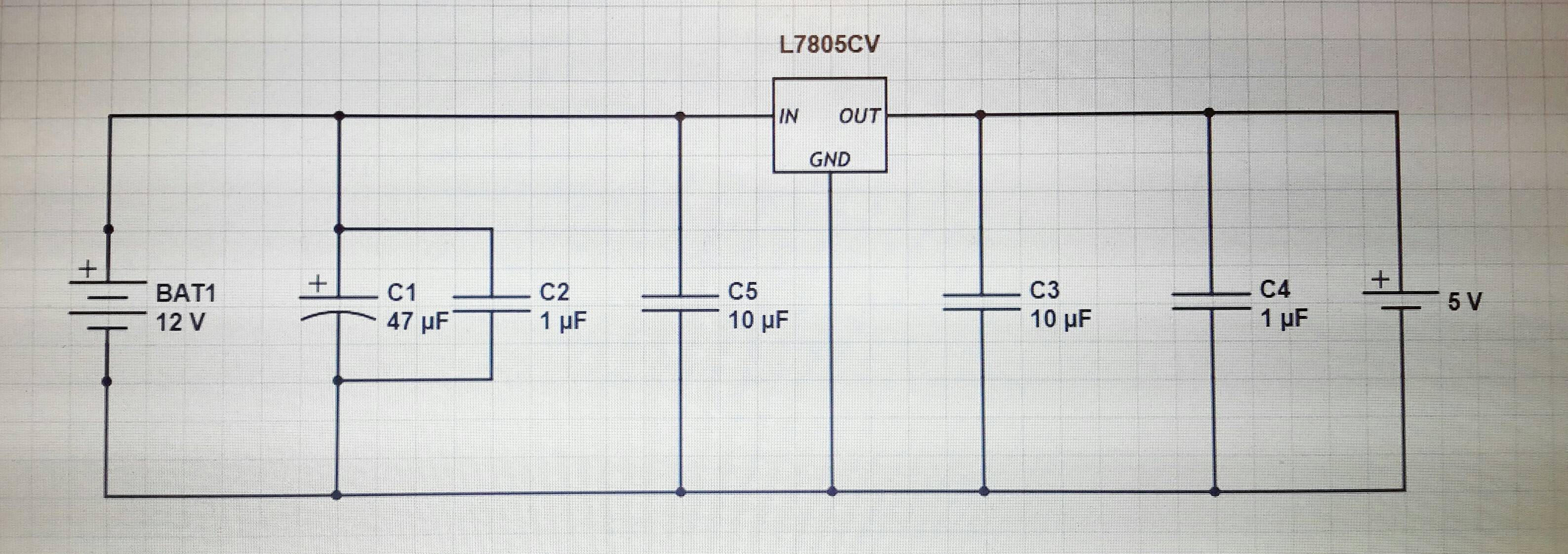
am a hobbyist with little prior electrical engineering knowledge so please bear this in mind! Trying to safely store and step down voltage from 12V to 5V using capacitors and L7805CV regulator.

Have been advised to follow the circuit for this below, however during testing there is a significant drop in voltage (measuring with multimeter at the points before and after C1 on circuit) and nothing appears to be getting to the 5V battery beyond the regulator.

circuit

1. What is the correct schematic? Since the above isn't working (preferable that circuit includes a voltage regulator and a capacitor)

2. Are the capacitors in the right place / correct values?

3. Capacitor C1 discharges very quickly, why is this? (>1 min charge goes down)

Thanks

Edit: noticing a number of comments unrelated to the above three q's, which was why this post was created. To save time I will not be responding to unrelated comments. Cheers

\$\endgroup\$
20
  • 1
    \$\begingroup\$ As in "to the left" and "to the right" of C1? They should all be the same voltage. Perhaps edit the picture to mark the exact points that you are measuring, and the voltages you get at each. \$\endgroup\$ Commented Mar 22, 2016 at 10:21
  • 1
    \$\begingroup\$ Unclear what "before and after C1" means; do you mean the multimeter (+) probe at different points along the +12V input wire to the 7805? \$\endgroup\$
    – MarkU
    Commented Mar 22, 2016 at 10:22
  • 3
    \$\begingroup\$ Might also help if you could post a photo of the actual prototype, since this is a very common type of circuit and it could either be a construction error or a measurement error. \$\endgroup\$
    – MarkU
    Commented Mar 22, 2016 at 10:24
  • 1
    \$\begingroup\$ Heat sinking will also be important; a 7805 is very inefficient at regulating 12V down to 5V. The heat loss will be (VIN-VOUT)*(whatever current the load draws). You may be surprised by how little load current it takes to make the bare 7805 really really hot. \$\endgroup\$
    – MarkU
    Commented Mar 22, 2016 at 10:27
  • 2
    \$\begingroup\$ The circuit diagram is fine. The problem is probably in the way you've constructed it (strongly hinted at by your statement "there is a significant drop in voltage (measuring with multimeter at the points before and after C1 on circuit)". Post a few good hi-res photos from different angles of what you've actually constructed and we might be able to see what you've done wrong. \$\endgroup\$
    – brhans
    Commented Mar 22, 2016 at 13:01

1 Answer 1

2
\$\begingroup\$

Capacitor C1 discharges very quickly, why is this?

Quiescent current (no load current) for a 7805 is about 5mA.

Q = CV or...

\$\dfrac{dQ}{dt}\$ = C \$\dfrac{dV}{dt}\$ = current

So 5 mA *\$\dfrac{1}{C}\$ = \$\dfrac{dV}{dt}\$ = 106 volts per second.

Or put another way, if you draw 5mA from a 47 uF capacitor charged to 12V, expect it to be fully depleted after 113 ms.

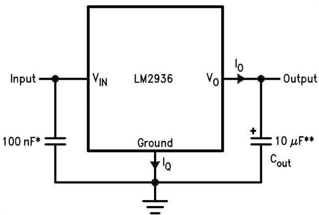
If instead of the 7805 you chose an LM2936 this time period would extend: -

enter image description here

Iq for this device is less than 15 uA for a no-load situation. This will extend the time period by about 333 times.

\$\endgroup\$

Not the answer you're looking for? Browse other questions tagged or ask your own question.