The Electric Field or E-field of high impedance noise can easily exceed 50 V/m from a nearby power line with 240Vrms or ~679Vpp. But at this high impedance fento-farads ) and high body dielectric constant there is very little current thru our body at 50 or 60Hz, and low voltage drop, since our body is many orders of magnitude lower impedance than the stray E-field coupling impedance C ( fento-farads ).
Yet somehow when we use a circuit board ( a different smaller CM antenna body with electronics) we see a big different in line frequency signals.
What should be done?
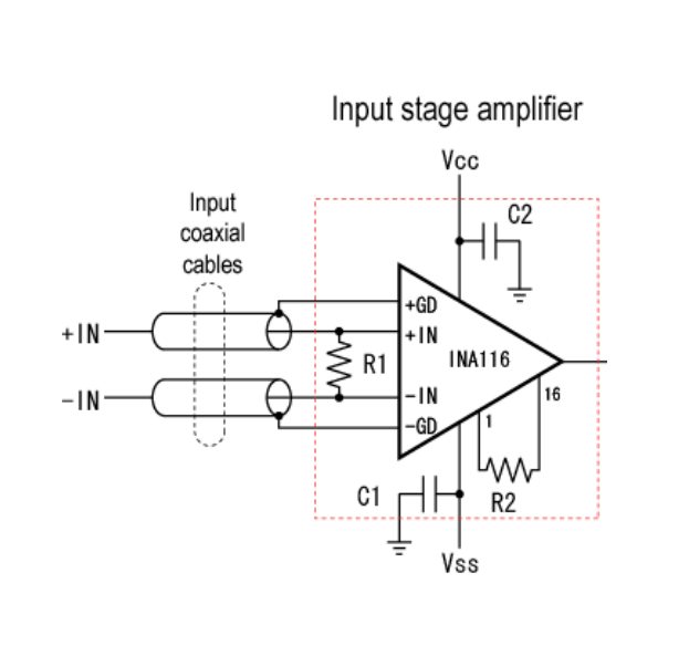
We need to use very high impedance differential amplifiers with very high COmmon Mode Rejection Ratio CMRR such as the ANA116
- First electrode impedance to the body must low ( by >4 decades lower than load) and the floating electronic amplifier ground must also be attached to the body so we increase the ratio between interfering source and low Guard Signal target impedance
- Second we balance all the signals so the amplifier has exactly the same high impedance using very low balanced current source inputs
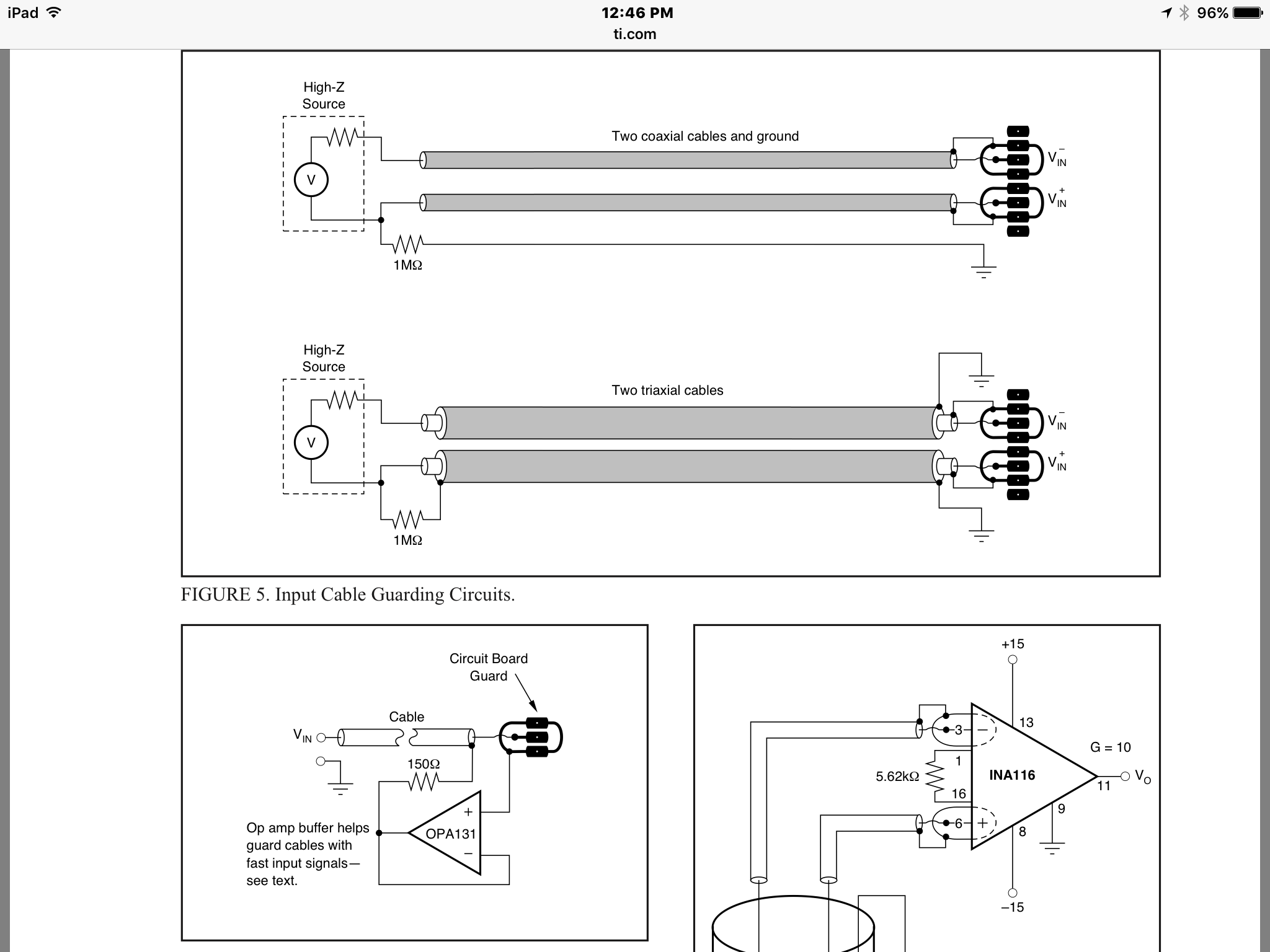
- Third by using an Active Guard coaxial shield
- Fourth by using the Bipolar Battery common as 2nd coaxial shield using triaxial cables
- by using a large CM choke to raise high frequency transient impedance to prevent excursion past the CM input range with an RF small load cap (matched pair)
- for lower AC response <<1Hz chopper stabilized INA's are used.
Consider high quality EEG's can achieve a low noise in the range of 1uV , that's a ratio of 8 decades or 160 dB for the best performing instruments or a CMMR of 160dB which is far greater than what an INA can do unless you use every method suggested in INstrument Amplifier (INA) Application Notes. (AN #)
 - You can make your own with the average of all electrodes and buffer that to create an active "virtual ground" using the +Gd and -Gd (guards) on the INA116
- For your situation, you might get satisfactory results with 120dB CMRR or you may need more, but you don't need ground but it would help to shunt stray E-Fields to another path thus lowering the E-Field levels.
- The guard current is limited by a high R series shunted by the electrode resistance. For a low impedance source a 150 Ohm buffered source is shown in the 3rd case below. The gnd is the twin battery centre voltage.
see below implementation for twin coax, twin triax and buffered twin coax.

- The most common practice uses "Right-Leg drive" to create a "Virtual Ground"
-The available features of many INA is make use of the low impedance "Guard" signal from each channel to shield the signal itself. This also enhances bandwidth by reduce the AC current and thus the Capacitance of the cable cancels out from Ic = C dv/dt where the dv/dt of the signal relative to the guard signal approaches zero for the Bandwidth of the amplifier.
However even "Guarding" has it's limits if the CM input exceeds the linear input range.
- So how can we create a virtual low impedance ground to shunt the high impedance C coupling of stray electric fields without coupling more noise?
- by reducing the CM current.
- How do reduce the CM current?
- 1) by shunting the E-Field voltage to a virtual ground
- 2) by raising the CM impedance to the differential mode (DM) signal without affecting the DM impedance.
What has been tried?
- use the center 0V of two batteries +/-V which is low impedance relative to the common mode supply rails on the amplifiers, and place that as a mid-point electrode away from muscle artifacts ( like a still leg).
How can that fail?
- the battery voltage differential creates a DC offset that must not be amplified by using a suitable DC cutoff.
- The ground path can act as another E-Field antenna with a slightly different path than the signals. It must be closely coupled to each signal with matched cables.
What is the most common practice?
- derive the Common mode signal taking the sum minus the difference and drive ta body electrode from an Op Amp (also known as = a.k.a.) e.g. "Right-Leg Drive"
What else is possible?
- using non-gel coupled electrodes at 0.1mm gap, with center pad and guard ring to measure the near-proximity electric field with active INA above round PCB Electrode
What is a good battery pair to use that are low impedance and stable voltage?
Other notes
- In your case with no Gnd avail, there is no conducted leakage to ground but also no EMI reduction as a result. So SMPS modulated noise, when radiated with the AM E-Field modulation coupled to the body and partially rectified by ESD protection diodes in the front end shows up as a CM noise factor. Thus the above methods may prove more challenging with SMPS supplies. Those with effective active PFC may be better. Typical Laptop chargers would be much worse. Linear supplies can be bad since the rectifier charge pulse currents can 10x the average discharge current as it is inversely related to %V ripple before regulation. These are some of the reasons Medical PSU's are more stringent and expensive as well better immunity from Power Line Transients when properly used.


