4
\$\begingroup\$

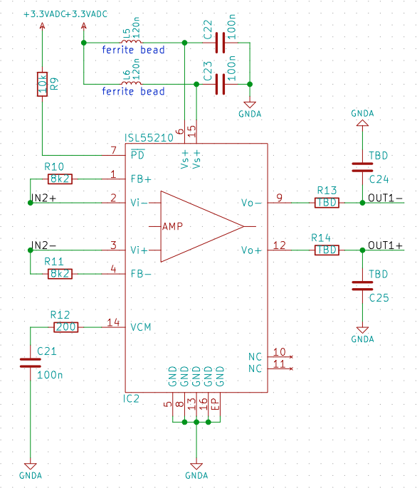
I have a fully diffrential opamp that is configured like seen in the below picture:

enter image description here

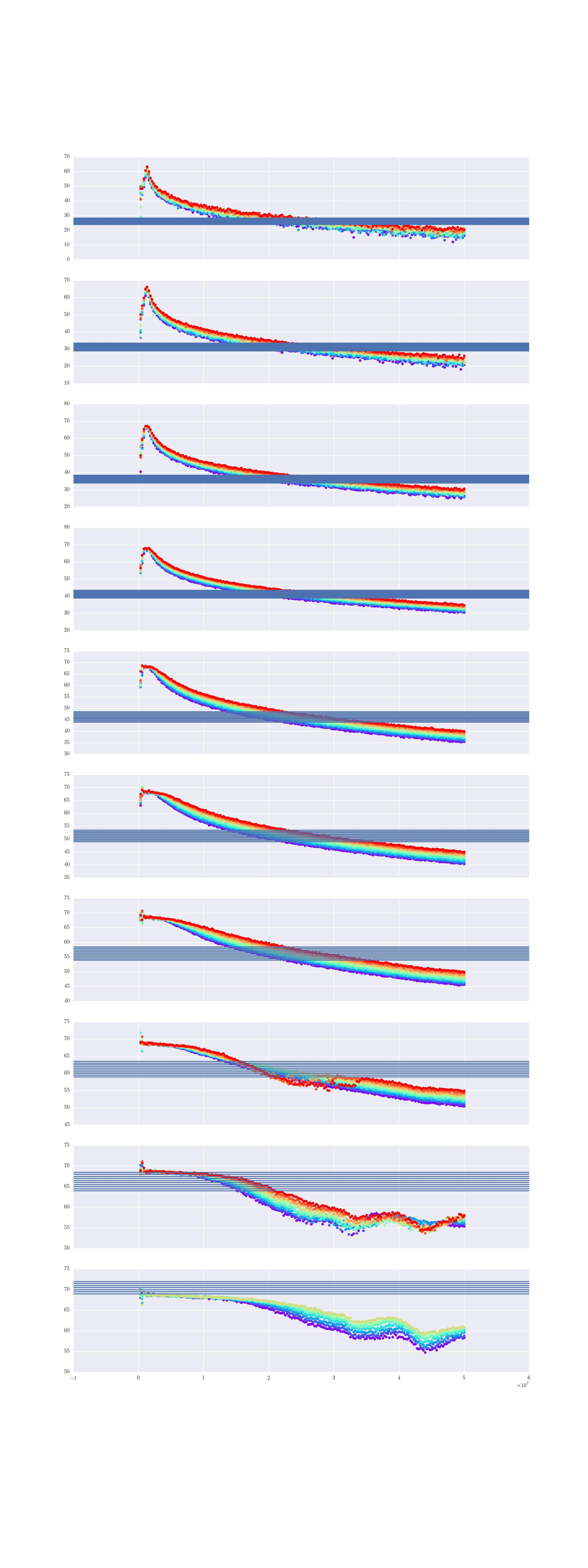
I have a series of Frequency sweeps (differently scaled input) that I performed and measured with a VNA. The weird part is that it looks so skewed:

enter image description here

Blue is the expected amplification according to calculations (should def. be true) while the colored dots are the sweeps at different input amplitudes each color.

The OpAmp s configured to amplify approximately 29dB. So according to the Datasheet this should be zero issue up until 100MHz (it's on page 6 of the ISL55210 DS). Since I sweep only up until 50MHz I am very confused how it results in this broken curve .. It's also not a circuit that's very complicated ...

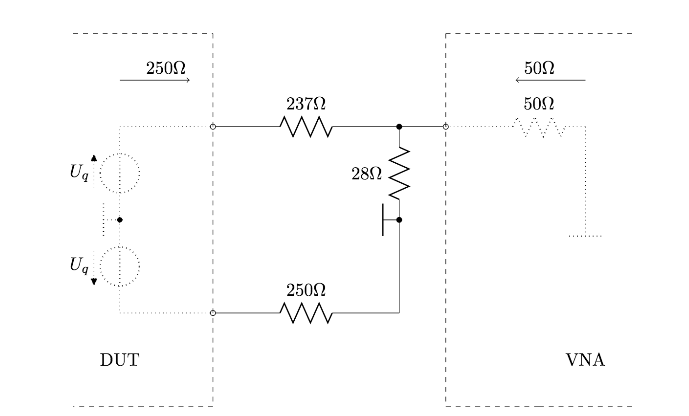
EDIT: I measure the DUT like seen below, except that there is a 1uF Capacitor in between the adaptor and the VNA to block any DC:

enter image description here

The input is generated by an AD8331 which works 100% properly as verified in separate measurements. The AD8331 is connected with two 270 Ohm Resistors.

I would be grateful for any hint what I could check ...

P.S. The peak at the beginning is not less strange ...

\$\endgroup\$
9
  • \$\begingroup\$ Seems you have some 1st order cut-off behavior. I see two RC networks at the output which could be responsible for this. I would also need to know all details of how you apply the input signal and measure at the output. Your VNA probably has 50 ohms inputs ? \$\endgroup\$ Commented Jan 15, 2017 at 21:31
  • \$\begingroup\$ I added the missing information and hope I didn't miss something again ... :) \$\endgroup\$
    – Yatekii
    Commented Jan 15, 2017 at 22:04
  • \$\begingroup\$ "I sweep only up until 30MHz" - So why do your plots go to 50 MHz? \$\endgroup\$ Commented Jan 16, 2017 at 2:38
  • \$\begingroup\$ How did you manage to come up with this impedance mismatched R network? How did you confirm there is no THD or compression in your results that could result in false fundamental s21 response. \$\endgroup\$
    – D.A.S.
    Commented Jan 16, 2017 at 3:43
  • \$\begingroup\$ @WhatRoughBeast Uhm of course it should be 50 MHz ... \$\endgroup\$
    – Yatekii
    Commented Jan 16, 2017 at 7:19

1 Answer 1

1
\$\begingroup\$

I don't know what you are expecting without using input resistors. At the moment you have a differential trans impedance amplifier and that will have virtually zero ohms input impedance. The AD8331 is a voltage output device so something looks very screwed up in your interfacing philosophy.

Try using input resistors in series with each input line and look at what the VGA output of the AD8331 is expecting to see - fig 57.

\$\endgroup\$
2
  • \$\begingroup\$ Hey! As mentioned: The AD8331 is connected with two 270 Ohm Resistors. :) This is not exactly 250 Ohms as expected but should work. Maybe you have overlooked that, maybe I have misunderstood your comment, then, sorry for that. \$\endgroup\$
    – Yatekii
    Commented Jan 16, 2017 at 13:00
  • \$\begingroup\$ It would be so much better if you drew a complete circuit than bits of circuit. So you are saying the AD8331 connects to IN2+ and IN2- with 270 ohm resistors. Also, can you properly explain the multi-coloured spectral graphs and what the different colours represent? \$\endgroup\$
    – Andy aka
    Commented Jan 16, 2017 at 13:16

Your Answer

By clicking “Post Your Answer”, you agree to our terms of service and acknowledge you have read our privacy policy.

Not the answer you're looking for? Browse other questions tagged or ask your own question.