0
\$\begingroup\$

I have two N-channel MOSFETs. I want to make a simple bidirectional solid state relay by using them. I want to place them back to back as seen in the schematic below, and drive them with a controlled gate signal. I will have two isolated voltage sources: \$V_g\$ and \$V_s\$.
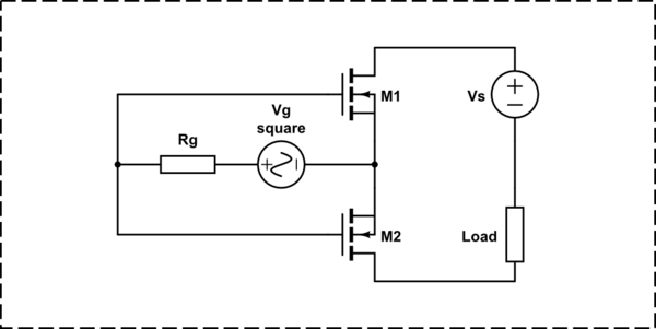
schematic

simulate this circuit – Schematic created using CircuitLab

I have no doubt that the simpler circuit in the below would work. But, in my circuit, the supply grounds are not shorted, and it is making me unsure. Consider swapping places of \$V_s\$ and the load in this second circuit, then a similar question arises.
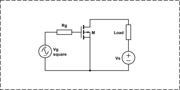
schematic

simulate this circuit

\$\endgroup\$
6
  • \$\begingroup\$ What matters is the voltage between the channel and the source. Are you relying on the body diodes though? \$\endgroup\$
    – pjc50
    Commented Feb 5, 2017 at 13:53
  • \$\begingroup\$ @pjc50 Yes, I'm relying on the body diodes. Shouldn't I rely on them? \$\endgroup\$ Commented Feb 5, 2017 at 18:06
  • \$\begingroup\$ I'm not sure what properties they have, especially durability, and they'll give you 0.7V of voltage drop and power dissipation. \$\endgroup\$
    – pjc50
    Commented Feb 5, 2017 at 18:11
  • \$\begingroup\$ @pjc50 Are you sure about the voltage drop and power loss? When the MOSFETs are off, there will no current flowing, thus no power loss. When the they are on, the channel of the MOSFETs will short their body diodes, so there will be at least theoretically zero voltage drop. \$\endgroup\$ Commented Feb 5, 2017 at 19:27
  • \$\begingroup\$ Body diodes tend to end up in the opposite direction to normal current flow in a lot of (but not all) MOSFET circuits, so unless you're careful, you might find that you end up with basically a diode that conducts in a direction other than the one you want, so you either have power flowing through the diode or through the diode and the switch (this is the result when building MOSFET 'ideal diode' circuits) \$\endgroup\$
    – Sam
    Commented Feb 6, 2017 at 1:00

2 Answers 2

1
\$\begingroup\$

the First circuit has no GND related issue. I am convinced with pjc50 and echo the same.

A common GND is important when you want to reference some voltage node with respect to a common node (GND). Here, you just require correct Vgs to turn on the MOSFET. Circuit 1 is correct.

The second model is not a correct model for bi-directional solid state relay since it can permit the load current in only one direction not in both direction.

In the 2nd circuit which you drew will work in the current orientation of the Vs, but when you reverse the Vs polarity the MOSFET won't conduct.

While the relative positions of Vs and Load will have no effect since they are in series.

\$\endgroup\$
1
  • \$\begingroup\$ The second circuit is just an example of having a common GND between the voltage sources. It is not supposed to be a bidirectional relay circuit. Thank you for your answer. \$\endgroup\$ Commented Feb 5, 2017 at 18:04
1
\$\begingroup\$

Yes you can. Here is one...

PCSA1-S5-S15-S (Power supply, 5V to isolated 15V)

http://www.digikey.com/product-detail/en/cui-inc/PCSA1-S5-S15-S/102-3948-ND/6181043

If you don't care about speed you can just turn the supply on and off.

If you care about speed one usually uses an isolated DC supply and an isolating gate driver. Like this one...

MGJ2D051505SC (Power supply 5V to isolated +15V/-5V)

http://www.digikey.com/product-detail/en/murata-power-solutions-inc/MGJ2D051505SC/811-2998-5-ND/4840065

1EDI60N12AFXUMA1 (Isolated MOSFET driver)

http://www.infineon.com/dgdl/Infineon-1EDI60N12AF-DS-v02_00-EN.pdf?fileId=db3a3043427ac3e201428e5da08f372a

One key factor when choosing a supply for gate drive is to pick one with a very low input to output capacitance. The MGJ2 series meets that criteria.

\$\endgroup\$

Your Answer

By clicking “Post Your Answer”, you agree to our terms of service and acknowledge you have read our privacy policy.

Not the answer you're looking for? Browse other questions tagged or ask your own question.