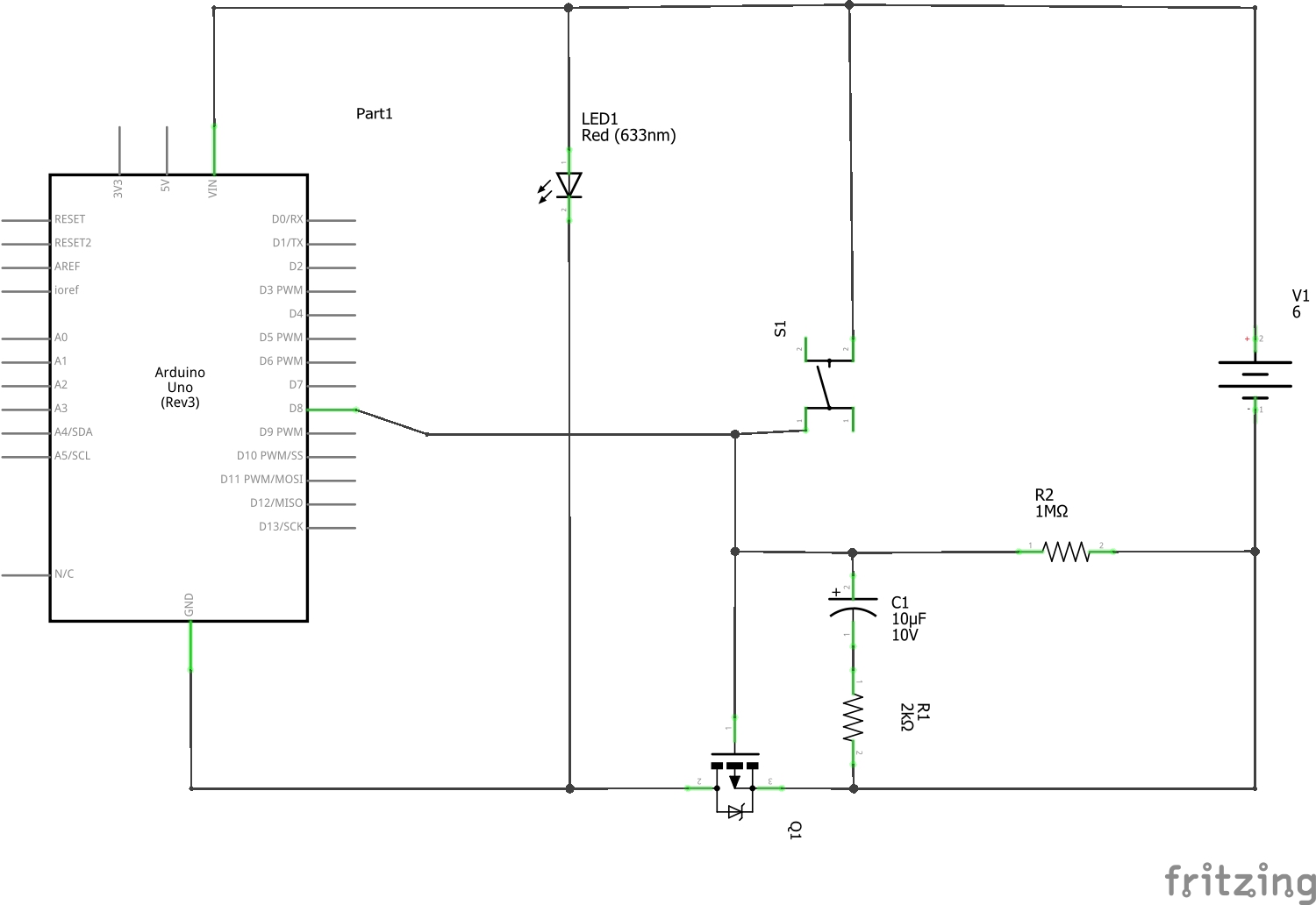
I want to make a simple battery powered Arduino-based keypad lock, and in order to save as much power as possible, I want it to self-shutdown after few seconds of inactivity.
I am trying to devise this shutdown mechanism and this is what I suppose should work:
It should work like this: after I tap the switch, MOSFET should start conducting, powering the Arduino and also C1 should charge quickly. C1 should keep MOSFET on for few seconds, allowing Arduino program to load and set D8 pin to logical 1, and therefore to take over business of keeping MOSFET on at all times. After Arduino detects few seconds of inactivity, D8 pin turns off and after C1 discharges, MOSFET turns off, so the whole thing turns off.
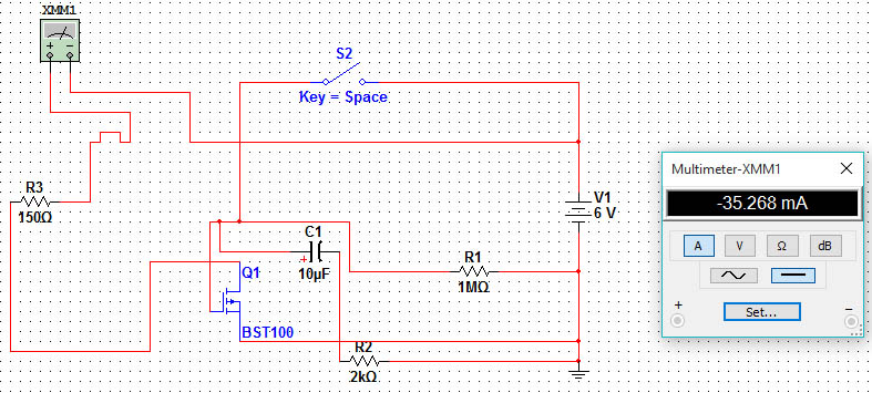
I've entered similar scheme in Multisim software, replacing Arduino with 150 ohm load resistor and ignoring the D8 pin. Unfortunately, Multisim says there is 35mA current through load resistor despite the fact switch is OPEN!! How is it even possible?
Multisim scheme:


