0
\$\begingroup\$

I am attempting to build a simple, mini USB UPS for my Rasberry Pi 3 to survive sudden, short-term voltage drops. I have built the working circuit below on a breadboard.

When the 5V supply is removed and the voltage level (from supercaps) drops to 4.3V (between Multi+ and Multi-), the circuit does not recover when the 5V supply returns.

At 4.4V and above, the circuit recovers and the supercaps recharge back to ~5.35V. If the circuit is stuck at 4.3V or below, and I remove the USB power to the RPi, the circuit recovers and the s-caps recharge to ~5.35V.

What am I missing or doing wrong, and/or how can I fix? Why wont the system bounce back to ~5V after the voltage level drops to 4.3V or below? Thank you in advance!

Update: schematic updated based on answer 13 JUN 17
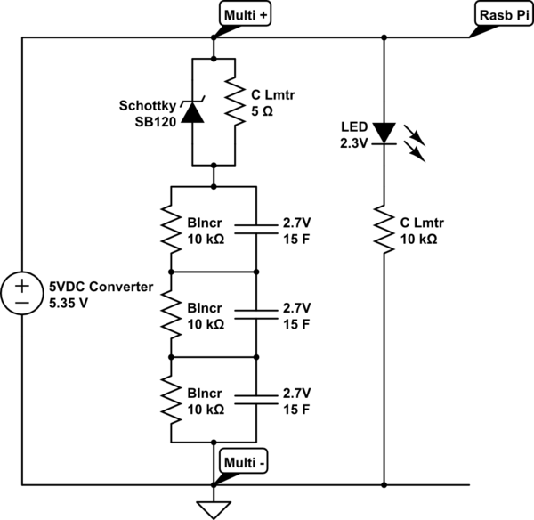
schematic

simulate this circuit – Schematic created using CircuitLab

\$\endgroup\$
9
  • \$\begingroup\$ That's a significant bleeder! Off topic but have you considered a buck -> 2.5 V cap bank -> boost to 5 V? Does your 5 V supply have any CC limit or does it simply shut down due to overcurrent? Have you tried a small resistor in series with your cap bank? \$\endgroup\$
    – winny
    Commented Jun 7, 2017 at 20:53
  • \$\begingroup\$ Your circuit diagram shows the ground side of the capacitors unconnected to the supply or load; hopefully that is a drafting error only. It's possible that when discharged your capacitors look too much like a short circuit and an overcurrent shutdown circuit in the USB power source activates, though the issue could readily be something else. Generally it's hard to build something like this right, and your proposal is likely far short of what is needed. \$\endgroup\$ Commented Jun 7, 2017 at 21:10
  • \$\begingroup\$ there's probably an inrush current that activates a protection mechanism. When you un+re-power the board, that protection mechanism might take a moment to kick-in, during which the caps charge up. the current consumption of the caps is proportional to the voltage difference; big diff, big current. no diff: no current, at max diff: max current. \$\endgroup\$
    – dandavis
    Commented Jun 8, 2017 at 6:49
  • \$\begingroup\$ All, thank you - any alternative suggestions? \$\endgroup\$ Commented Jun 8, 2017 at 9:03
  • \$\begingroup\$ Why are you using three caps where two would be sufficient? \$\endgroup\$
    – JimmyB
    Commented Jun 8, 2017 at 9:18

1 Answer 1

5
\$\begingroup\$

The 1 ohm balancing resistors are completely inappropriate. Without the capacitor spec sheets, I would estimate their values should be north of 10k each. They may not even be necessary given the 2.7 volt rating of the caps. As they are, the capacitors will never correctly charge and the 3 ohm series string is a substantial load to the supply. Hopefully this is a drafting error that you can comment on and correct.

The negative lead of the cap bank is isolated from the 5.35 volt negative. This is not correct. It should be tied to the negative rail.

I would also be concerned about the surge current when the caps are largely depleted. At this point, they are effectively a short circuit to the USB supply. This may be what you are seeing. Try placing a 10 ohm or so resistor in series with the cap bank to see if this corrects your problem. This will increase the charge time but limit the initial charge surge.

\$\endgroup\$
8
  • \$\begingroup\$ Thank you for the notes - the balancing resistors were 1k ohm each and the bank is attached to gnd. Edited schematic. \$\endgroup\$ Commented Jun 8, 2017 at 8:55
  • \$\begingroup\$ I havent let the s-caps discharge all the way to ~1V or less. During testing, I noted that when the caps fell to ~4.3V (or below) and the 5V power supply was brought back, the s-caps failed to charge and the whole circuit only saw <=4.3V (wherever the discharging voltage was when the power supply was brought back). However, when the caps only fell to ~4.4V or greater, it was still enough to recharge the circuit when the power supply came back. FYI - the 5VDC supply is a 220VAC - 5VDC power supply for a microUSB cable, which has been cut in half and my circuit added. \$\endgroup\$ Commented Jun 8, 2017 at 9:01
  • \$\begingroup\$ 1) Balancing resistors/circuits are needed, else you will get imbalance and reduced performance from or damage to the caps 2) A 10 Ohm resistor in series with the caps will drop too much voltage to power the Pi; one could try an anti-parallel (Schottky) diode across the resistor though. \$\endgroup\$
    – JimmyB
    Commented Jun 8, 2017 at 9:16
  • \$\begingroup\$ JimmyB, you're suggesting adding the 10 ohm resistor in series with the bank and then also adding a Schottky in parallel with that resistor? What is the purpose of the Schottky in that position? I was thinking of placing a 4.7Vf Schottky in series between my parallel circuit and the RPi, to shunt current from the RPi when the s-cap voltage discharges to 4.7V, which would then push all current to charging the s-caps? \$\endgroup\$ Commented Jun 8, 2017 at 9:33
  • 1
    \$\begingroup\$ @jimmyB I placed a 5 ohm resistor and anti-parallel schottky diode (SB120), together in parallel, in series with the s-cap bank and 10k ohm series balancing resistors - it appears to be working. Edited the schematic w the updates. Thanks all! \$\endgroup\$ Commented Jun 13, 2017 at 10:32

Your Answer

By clicking “Post Your Answer”, you agree to our terms of service and acknowledge you have read our privacy policy.

Not the answer you're looking for? Browse other questions tagged or ask your own question.