4
\$\begingroup\$

Because I am working on some AVR microcontroller projects that will have multiple processors sharing clocks, I wanted to create a solid, reliable circuit to provide a clock after changing the AVR fuses, just in case. ;)

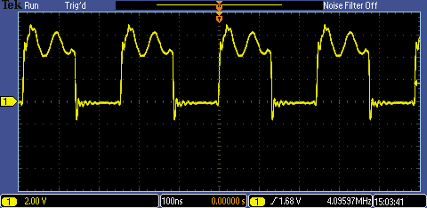
I created a Pierce oscillator at 4.096 MHz and it gives a decent signal and near-perfect frequency with a very good vertical slope to the edges, but it has a lot of non-square jiggles in it:

enter image description here

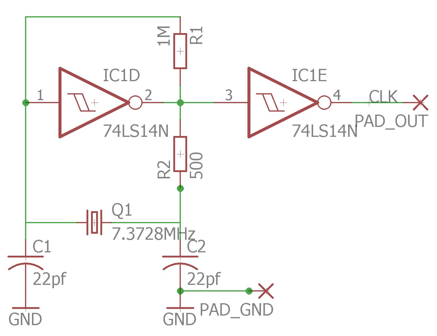
Here is my circuit:

enter image description here

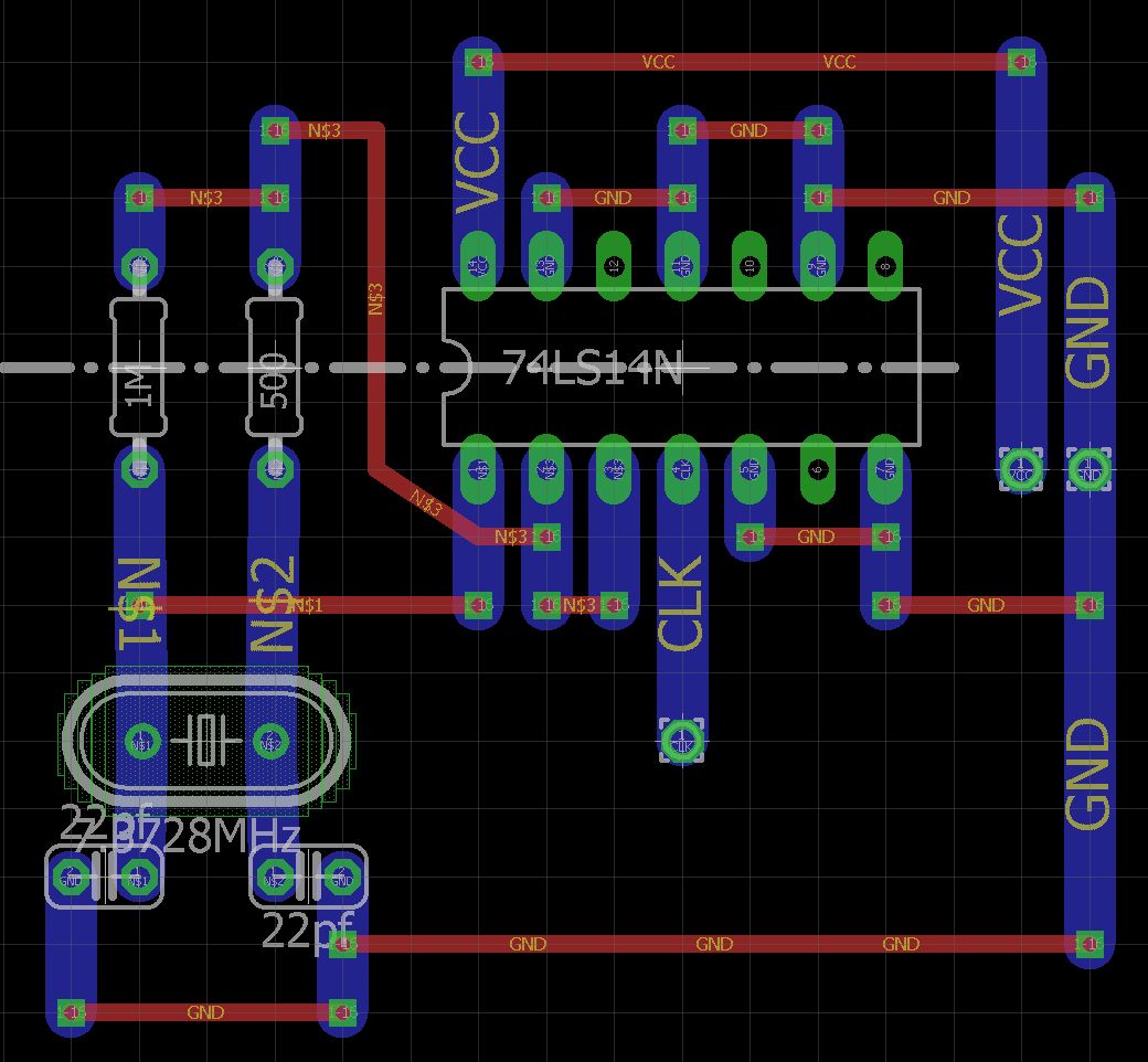
And its realization on genuine Veroboard: enter image description here

The question is: What can I do to remove most or all of the "spiky" signal components when the signal is high? Are there additional components I could add to condition that out and still have a usable square wave for clocking an AVR that is dependent on an external clock?

\$\endgroup\$
10
  • 3
    \$\begingroup\$ You are missing decent decoupling on the Vcc right next to the chip \$\endgroup\$
    – user16222
    Commented Jan 15, 2018 at 22:29
  • \$\begingroup\$ What sort of decoupling would you suggest? A capacitor of what size and type (if that's what you mean)? \$\endgroup\$
    – TomServo
    Commented Jan 15, 2018 at 22:33
  • 2
    \$\begingroup\$ Scope Vcc. Is it a flat line? \$\endgroup\$
    – τεκ
    Commented Jan 15, 2018 at 22:33
  • 2
    \$\begingroup\$ 100nF and a 10nF ceramic right on the Vcc pin. Also a 1uF near where Vcc comes in \$\endgroup\$
    – user16222
    Commented Jan 15, 2018 at 22:33
  • \$\begingroup\$ @JonRB That helped quite a bit. I'll accept that as an answer or answer it myself if you don't care to and update with a better picture. \$\endgroup\$
    – TomServo
    Commented Jan 15, 2018 at 22:51

2 Answers 2

3
\$\begingroup\$

A Pierce XTAL oscillator is a linear negative feedback with 180 deg phase shift and 180 deg inversion resulting in a stable AC saturated oscillation .

The negative DC feedback R acts as a low pass filter such that it self-biases the input for an output of 50% duty cycle.

A Schmitt trigger Relaxation oscillator is what you have shown which relies on the hysteresis between two thresholds to make an Astable relaxation oscillator. Except you have a TTL part number instead of CMOS. hmm.

So the problem is you cannot use hysteresis in a Pierce Oscillator.
It must be a linear inverter.

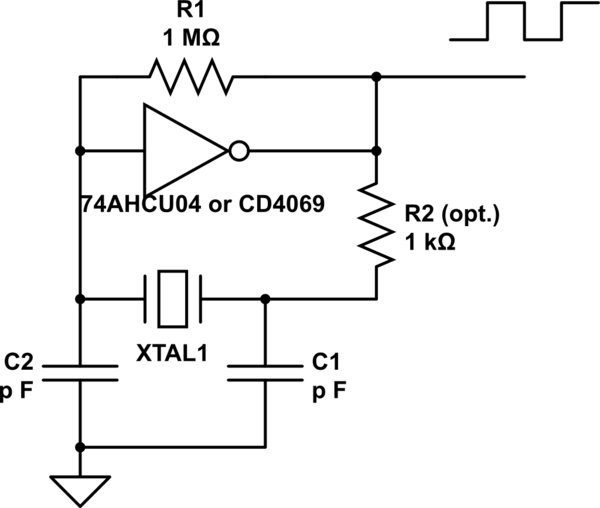
Often preference to UB or Unbuffered inverters is suggested to prevent resonance at overtones from the high gain, although this can be attenuated with a series R on the output to act as a LPF.

schematic

simulate this circuit – Schematic created using CircuitLab

Unfortunately there are some sites with false information about this circuit and its theory of operation. This site is an example which shows the Schmitt trigger. This is completely wrong and no uC uses a Schmitt trigger internally for external resonators.

\$\endgroup\$
2
\$\begingroup\$
  1. You aren't powering the inverters!!
  2. Oh, wait, that's a error in the schematic. Still bad though. This error leads directly to:
  3. Because you aren't showing how the inverters are powered in the schematic, it makes it less obvious that you forgot the bypass cap.

Do it right. Show everything in the schematic, including how ALL the chips are powered. Digital chips like this need a bypass cap between their power and ground pins as close to the chip as possible. A 1 µF ceramic would do nicely.

The fact that the tops of the waveforms are messy, but the bottoms clean, is a immediate clue that the mess is actually coming from the power.

Think about it. When the digital output is high, it's basically connected to Vdd via a FET of maybe a few 100 Ω at most. If there is crap on the output with nothing loading it, then that crap is coming from Vdd. Hmm. How did that get past bypassing at that frequency? Oh, look, there's no bypass cap! This really should have been a fairly obvious thought process.

A additional problem is that you are using 74LS parts to drive the crystal. A 1 MΩ feedback resistor isn't going to do much across a 74LS inverter. The resulting hard edges are causing significant harmonic content out of the crystal, which is ringing so hard that it's polluting the power supply, which is helped along by deciding to leave off the bypass cap. It looks like your noise is the 4th harmonic, almost certainly caused by the crystal.

Use a CMOS inverter with balanced input levels (not TTL), add the bypass cap, and everything should be significantly cleaner.
\$\endgroup\$
9
  • \$\begingroup\$ I moved the power connections to another schematic sheet. Thanks for the rule of thumb, that makes perfect sense and when I added the 1uF capacitor most of the AC artifacts went away. \$\endgroup\$
    – TomServo
    Commented Jan 15, 2018 at 22:55
  • \$\begingroup\$ @Tom: It's OK to be learning and asking about things new to you. But don't ask about more advanced concepts when you skipped over or are still confused by basic things like bypassing. If you're not sure what that is, then ask about that. It's like asking how to change the piston rings when you're not sure how to use a wrench. It's OK not to know how to use a wrench, but then ask about that before getting into things that assume you know wrench usage. \$\endgroup\$ Commented Jan 15, 2018 at 23:04
  • \$\begingroup\$ +1 for getting to the point-in a round about way. Your last 2 paragraphs get to the essence of the problems. Lack of bypass caps and a design that rings like a bell. Someone else gave you a -1. Not sure why... \$\endgroup\$
    – user105652
    Commented Jan 16, 2018 at 2:53
  • \$\begingroup\$ There are DIP sockets with built in bypass capacitors, those might be worth looking into. \$\endgroup\$
    – Oskar Skog
    Commented Jan 16, 2018 at 7:16
  • \$\begingroup\$ Can't anyone else see the fundamental flaws errors with this design. The signal is clearly TTL with high impedance resonance above 2V and you must use this LS14 with this design. It must be CMOS linear. TTL output impedance is non-linear. Low at 0V medium at 2V and high above 2V. \$\endgroup\$
    – D.A.S.
    Commented Jan 16, 2018 at 17:32

Your Answer

By clicking “Post Your Answer”, you agree to our terms of service and acknowledge you have read our privacy policy.

Not the answer you're looking for? Browse other questions tagged or ask your own question.