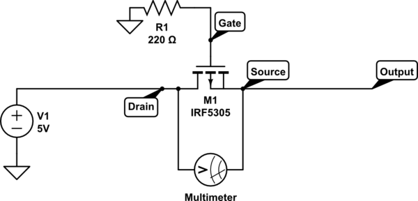
I'm using the P-Channel MOSFET IRF5305 (Datasheet: http://docs-asia.electrocomponents.com/webdocs/0791/0900766b807910f6.pdf) as an 'ideal diode.' However, it is not behaving like an ideal diode.
To better understand what is going on, I have connected two different multimeters between the Drain(D) and Source(S) of the MOSFET at different times. They indicate large resistance between D and S when V_GS is equal to zero. This particular MOSFET has a threshold of V_GS somewhere between -2V and -4V (from datasheet).
In my operation, I have grounded the Gate through a pull-down resistor to discharge any gate capacitance between switching. I have connected a 5V DC power source to the Drain of the MOSFET, and there is a larger than expected voltage drop between Drain and Source of the MOSFET. The multimeters indicate R_DS is about 200 Ohms (the datasheet for this MOSFET indicates R_DSON as low as 0.06 Ohms). Is there something I'm doing wrong or some factor I have not considered?
For clarity: The MOSFET has 1 Ohm or less resistance when I have the output (from the Source) open-circuited. But when I connected a 5W 22 Ohm resistor as the load, there was a significant voltage drop at the MOSFET.
EDIT: schematic included. I intend to use some control at the Gate of the MOSFET. The resistor is there to discharge any voltage at the gate that accumulates whilst the gate is HIGH due to the gate capacitance.
EDIT: The voltage drop I observed when I connected the 5W 22Ohm resistor was about 0.4V. The multimeter is being used in a 'resistance' mode and I am connecting it directly to the Drain and Source legs of the MOSFET. I am not calculating the resistance from a Voltage or Current measurement.

simulate this circuit – Schematic created using CircuitLab
