1
\$\begingroup\$

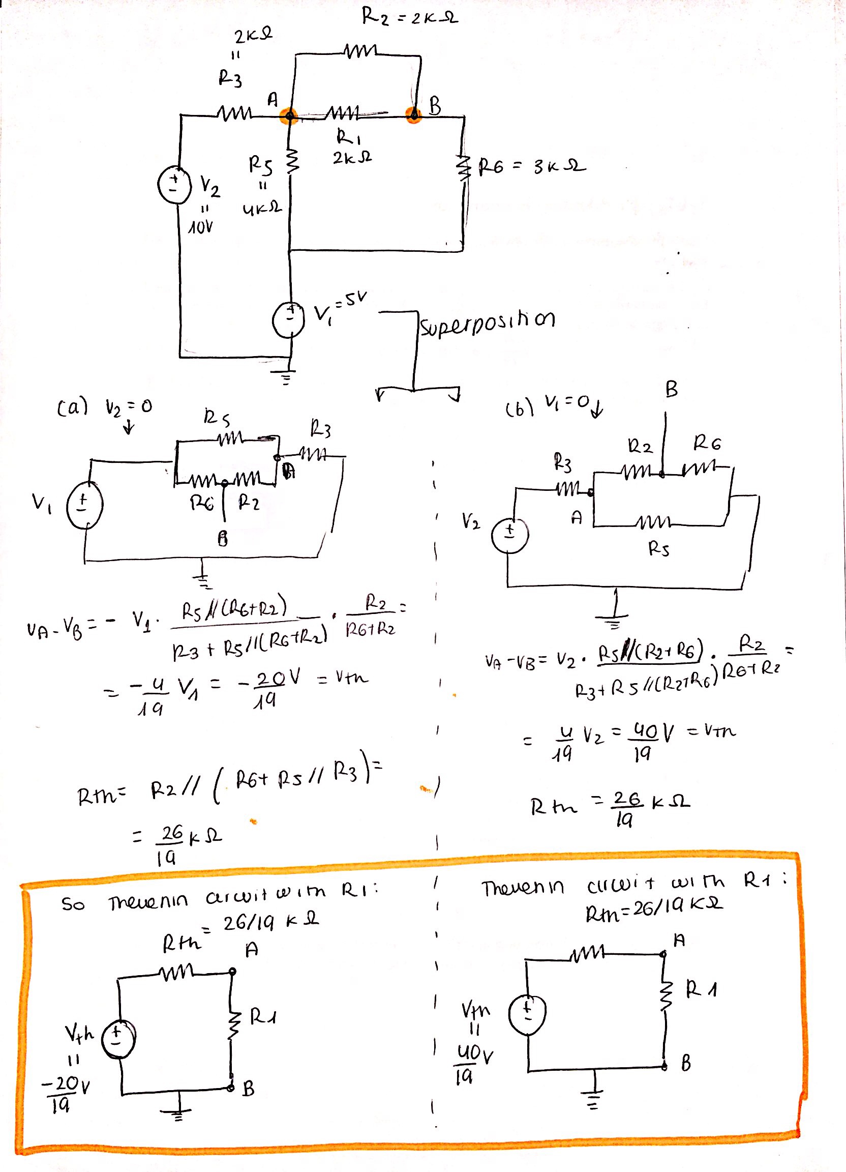
I am asked to find the equivalent Thevenin circuit between nodes A and B of the following problem, removing R1. I have attached my work because I have no idea if this is completely correct or totally wrong. Can someone please take a look at it? I would really appreciate it. enter image description here
Also, if they had asked me to calculate the Thevenin circuit between the nodes that limit R6, could this have been a good starting point, or would it be incorrect? enter image description here
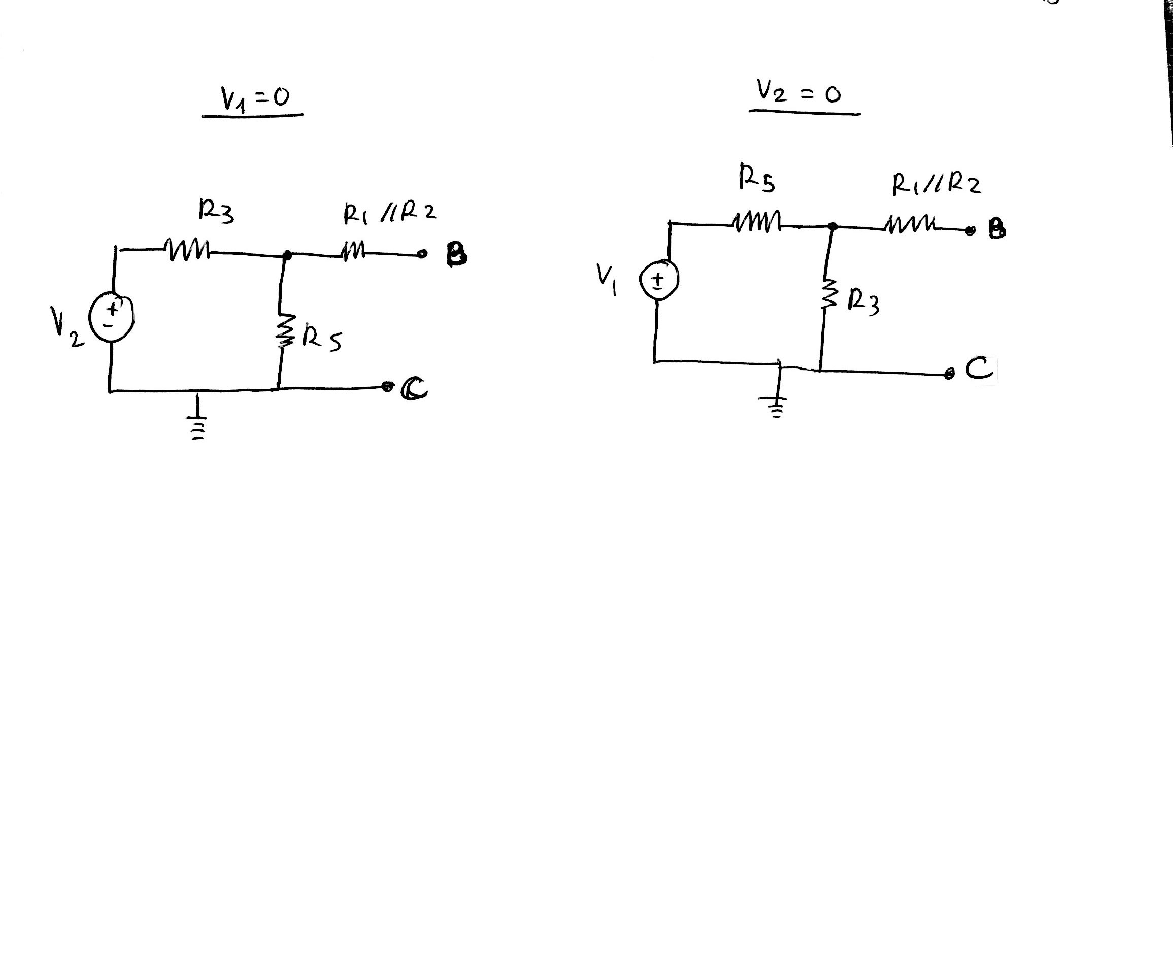
I am not sure if I am removing the resistances properly in both cases.

Thank you for any help!

\$\endgroup\$
0

2 Answers 2

1
\$\begingroup\$

Yea you are doing it right. In the first case you have to add both \$ V_{AB} \$ voltages to get the net voltage across A and B, when both voltage sources are present. With which you can draw the overall thevenin equivalent ckt. Second case is right too. Since there is no current through the R1||R2, the open circuit voltage \$ V_{BC} \$ will be nothing but voltage across R5 and R3 respectively in the last two circuits you have drawn.

\$\endgroup\$
0
\$\begingroup\$

You haven't used \$\small R_1\$ in the analysis. \$\small R_{TH}=\large\frac{13}{16}\small \:k\Omega\$.

\$\endgroup\$
3
  • \$\begingroup\$ I did the analysis treating $R_1$ as the load resistance, so I removed it. Is this not correct? Also, is the voltage okay? \$\endgroup\$
    – Bee
    Commented Mar 15, 2018 at 9:30
  • \$\begingroup\$ If that's the case then the question should state it. We can only go by what you've uploaded! \$\endgroup\$
    – Chu
    Commented Mar 15, 2018 at 11:34
  • \$\begingroup\$ Okay. My bad. I just edited it. Then, is my work correct? \$\endgroup\$
    – Bee
    Commented Mar 15, 2018 at 11:50

Your Answer

By clicking “Post Your Answer”, you agree to our terms of service and acknowledge you have read our privacy policy.

Not the answer you're looking for? Browse other questions tagged or ask your own question.