1
\$\begingroup\$

I've been looking at various valve guitar amplifier circuits and in specific, the power supply section.

I've been seeing a particular circuit that's repeating itself here and there in the power supply stage of various amplifier schematics.
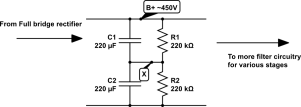
schematic

simulate this circuit – Schematic created using CircuitLab

Am I on the right lines by guessing that node X is some sort of virtual ground which is held constant by the voltage divider formed by the identically sized resistors? As in node X will be held at ~275V and any noise/variation/ripple to upset that will be "soaked up" by the capacitors?

I still don't understand why they wouldn't simply use a single big capacitor instead of this circuitry? The node X is not used anywhere and it seems to be there simply to aid filtering of the output of the bridge rectifier. Not to mention power losses due to the resistors. Atleast around 1W.

How about tolerances, obviously the resistors are not identical in real life, and such the voltage can't be half of B+. What implications does this have on the behaviour? Similarly capacitors have variance too.

\$\endgroup\$
0

2 Answers 2

1
\$\begingroup\$

The intent of the resistor voltage divider is to ensure that the 450 volts is divided (approximately) equally between the two capacitors.

Perhaps capacitors rated at more than 450 volts were not available, so two lower-voltage capacitors were used in series. Due to the variation of the capacitor's values, and leakage current in the cvapacitors, the applied voltage likely won't be split evenly between the capacitors if the resistor voltage divider was omitted.

\$\endgroup\$
6
  • \$\begingroup\$ What would happen if we put the capacitors in parallel? Would that not solve the voltage problem? \$\endgroup\$ Commented Feb 19, 2014 at 18:58
  • 2
    \$\begingroup\$ If the caps were parallel, each of them would see 450 V across itself, and a 450-V (plus margin) rated cap would be more expensive than a 250-V rated cap. \$\endgroup\$
    – The Photon
    Commented Feb 19, 2014 at 19:00
  • \$\begingroup\$ But I thought the voltage rating was more to do with how much charge a capacitor holds? I've heard of people who parallel capacitors in order to increase the voltage rating of 2 inferior ones. \$\endgroup\$ Commented Feb 19, 2014 at 19:07
  • 1
    \$\begingroup\$ The voltage rating of a capacitor is the maximum voltage that can be safely applied to it - if you apply a greater voltage, the capacitor may be damaged. Paralleling capacitors will not increase the voltage rating of the combination above that of the lowest-rated capacitor. \$\endgroup\$ Commented Feb 19, 2014 at 19:13
  • \$\begingroup\$ Ah ok. So then is the voltage rating literally the voltage the plates can withstand, regardless of their areas? I think I maybe confused total capacitance with voltage rating. \$\endgroup\$ Commented Feb 19, 2014 at 19:47
1
\$\begingroup\$

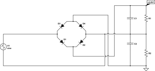
Sometimes a configuration like that is used that as point X connected as shown.

This is a full-wave voltgage doubler. By opening the connection to point X, the output voltage can be reduced from \$2.8 \cdot V1{(RMS)} \$ to \$1.4 \cdot V1{(RMS)} \$

schematic

simulate this circuit – Schematic created using CircuitLab

I don't know if there is actually such a connection in your circuit, but it would allow a cheaper winding to be used. As far as wasted power from the resistors, they probably want to make sure the capacitors discharge quickly so that they don't electrocute any musicians unnecessarily, and in any case a tube (valve) amplifier is hardly going to miss a watt or three.

\$\endgroup\$

Not the answer you're looking for? Browse other questions tagged or ask your own question.