1
\$\begingroup\$

I'm completely stumped on where to start with this, any point in the right direction would help. The work gave me a circuit drawn out and asks 2 questions:

1)Determine the number of transistors required to build the Canonical expression 2)Determine the number of transistors required to build the minimal SOP expression

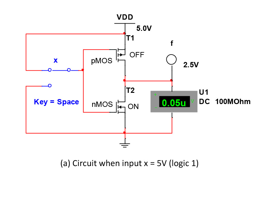
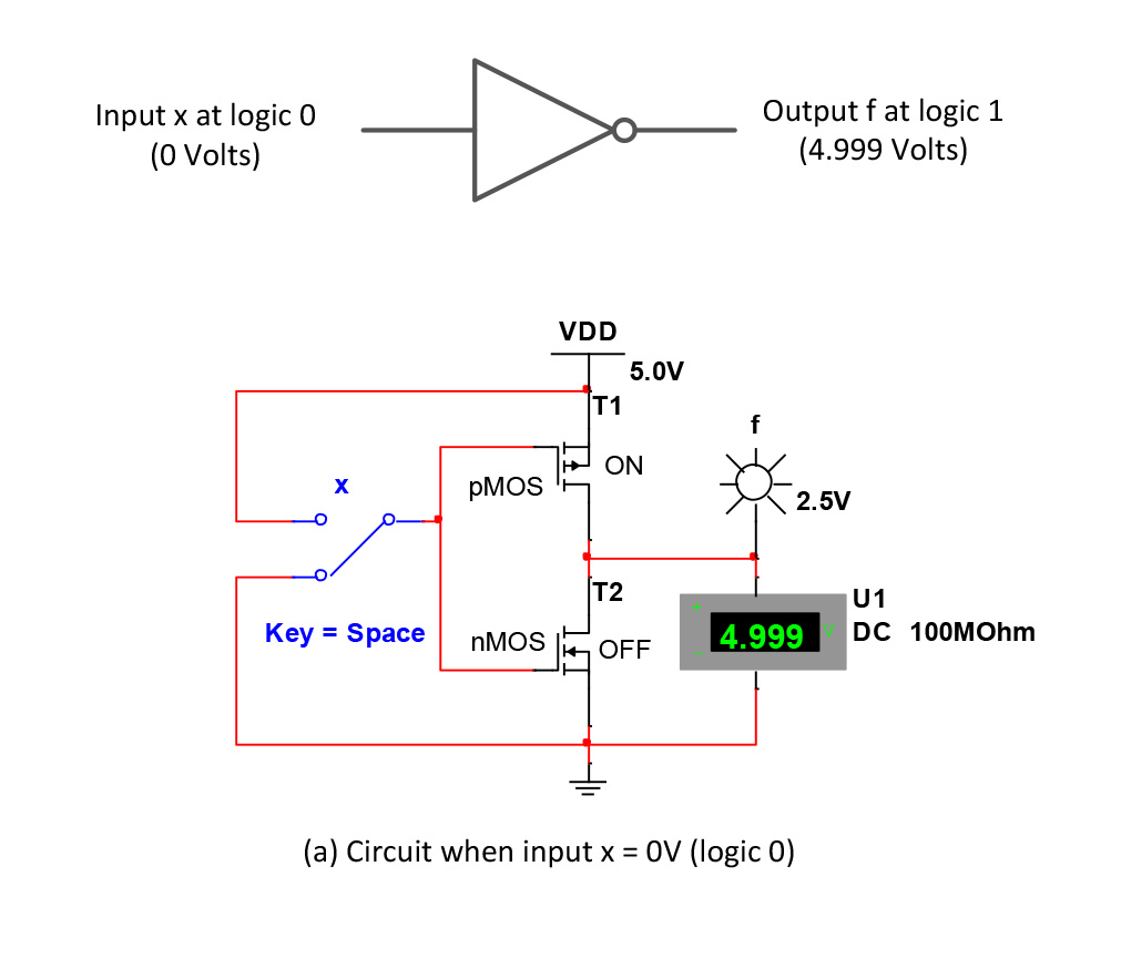
I don't know where to start and have read what I could, I just need some help starting and understanding how to work this out. I can show the circuit if necessary. There's a circuit showing input x at logic 0 (0 Volts) and output f at logic 1 (4.999 Volts) and all the other details like nMOS, pMOS, VDD, off, on, etc. What do I usually need to learn to understand how to find the number of transistors? Sorry for a dumb question because I know how simple this possibly could be.

EDIT:

Here's one of the pictures:
enter image description here

enter image description here

enter image description here

enter image description here

\$\endgroup\$
3
  • \$\begingroup\$ Just cut and included the image. I just don't want it to feel like I'm asking for the answer. I just want to understand how to do it. @PeterJ \$\endgroup\$ Commented Feb 23, 2014 at 10:00
  • \$\begingroup\$ That makes it clearer now by having a starting point. I can't answer it well myself but it should be possible to get a few pointers in the right direction like you're after. \$\endgroup\$
    – PeterJ
    Commented Feb 23, 2014 at 10:08
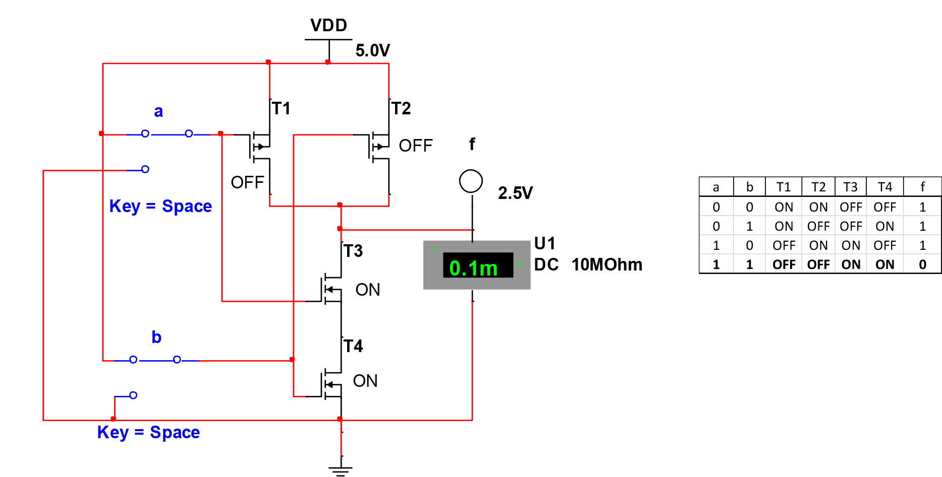
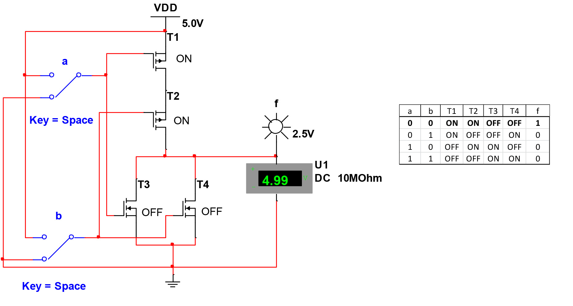
  • \$\begingroup\$ The last two circuits (with four transistors each and truth tables) are NAND and NOR gates respectively. \$\endgroup\$
    – tcrosley
    Commented Feb 24, 2014 at 5:25

1 Answer 1

1
\$\begingroup\$

I am not familiar with the SOP and canonical terms since I did not study electronics in English, but this seems about Boole logic stuff.

May I suggest you took a look there : http://sce.umkc.edu/~hieberm/281_new/lectures/forms-of-bool-expressions/forms-of-exprs.html and there : How to convert an expression from SOP to POS and back in Boolean Algebra? for example, because I would have trouble explaining all of this to you in English.

Then the logic gate in your picture is basically an inverter (a.k.a. "not" gate, see here http://en.wikipedia.org/wiki/Logic_gate). As the name more or less indicates you get at the ouptut the logic level "inverse" (exact term?) of your input (e.g. apparently TTL, +5V out for 0V in, in your case).

This looks a lot like homework, and I'm not yet familiar with the rules about that here, yet I'd rather you look a little more into it first. I'll be glad to help you then (with some reasoning to confirm or more specific questions ?).

\$\endgroup\$
8
  • \$\begingroup\$ There's not really a strict rule about homework, but generally a few hints in the right direction (as you've done) is fine while many don't like a complete answer that could be a copy/paste solution to their homework. \$\endgroup\$
    – PeterJ
    Commented Feb 23, 2014 at 10:30
  • \$\begingroup\$ It helps, I do understand that but what I don't really understand is what to do here and how to start it with the picture. \$\endgroup\$ Commented Feb 23, 2014 at 19:49
  • \$\begingroup\$ @user2318083 Well you gave only "one of the pictures", so it's difficult to get a good idea... Are there more logic gates or schematics ? You need to write the output as a result of the inputs. You do realize the similarity between the logic gate and the circuit with the MOSFETs, don't you ? Are you familiar with the Karnaugh map ? \$\endgroup\$
    – FredP
    Commented Feb 23, 2014 at 21:39
  • \$\begingroup\$ @FredP There are more but from what I understand those are separate, I could be wrong though since I'm already puzzled at the moment. I don't know about MOSFETs and I'm very familiar with Karnaugh maps. It's just the very first time I've seen this and never even had any idea of it before this. The professor kinda threw this at us. I can go ahead and upload the rest if that'll help. It'll be in the original post within a few minutes of this post. \$\endgroup\$ Commented Feb 23, 2014 at 22:07
  • \$\begingroup\$ @user2318083 Take a look here en.wikipedia.org/wiki/MOSFET you might recognize something from your schematic, and I insist on the similarity with the logic gate. If the rest is really separate (are you sure ?) I don't think you need to post all, maybe just another example. \$\endgroup\$
    – FredP
    Commented Feb 23, 2014 at 22:13

Your Answer

By clicking “Post Your Answer”, you agree to our terms of service and acknowledge you have read our privacy policy.

Not the answer you're looking for? Browse other questions tagged or ask your own question.