3
\$\begingroup\$

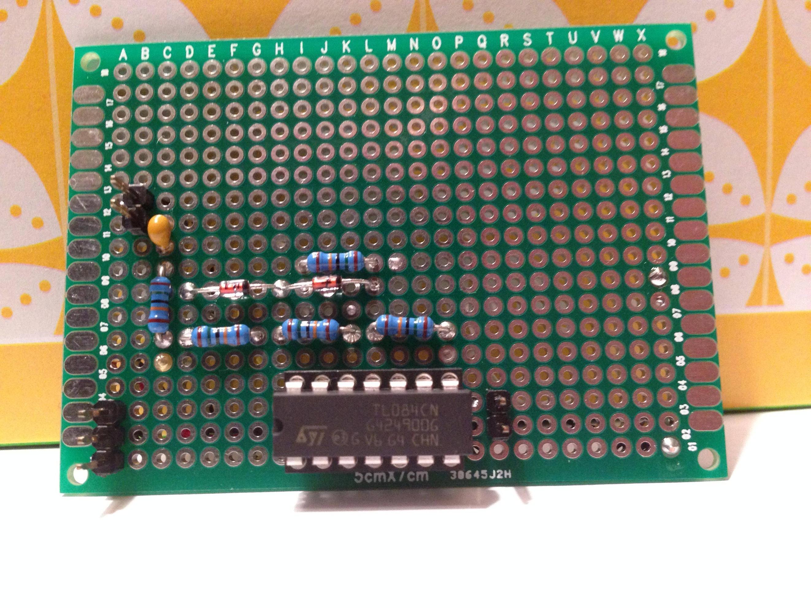
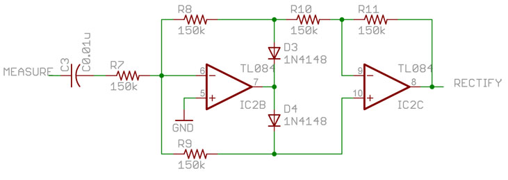
I'm building a "precision rectifier" using an op amp and some diodes. The schematic is attached. On a breadboard, this circuit behaves as expected, producing a clean, rectified sine wave. When I transfer the circuit to a protoboard, I get the signal shown in the attached scope capture. One side of the sine looks clean and the other is noisy. I've done this twice now, with the same results! Any ideas?

One possible culprit... I'm driving the input with an iPhone signal generator app, because I don't have a proper function generator. Maybe it's not up to the task? It seemed to work fine when the circuit was on the breadboard. I've rung the circuit out multiple times with a multimeter and I'm still not sure what's going on here.
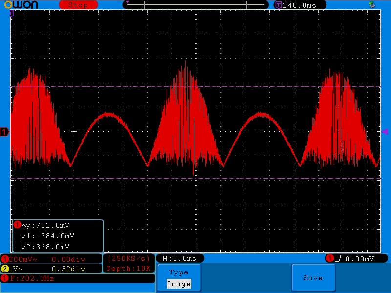
Scope Capture

Schematic

Board front

Board back

\$\endgroup\$
2
  • \$\begingroup\$ What are the power supply voltages for the opamps? \$\endgroup\$
    – Joe Hass
    Commented Feb 23, 2014 at 18:33
  • \$\begingroup\$ The supply is +/- 9V, from two 9V batteries. \$\endgroup\$
    – user37662
    Commented Feb 23, 2014 at 19:39

3 Answers 3

3
\$\begingroup\$

That's not really a precision full-wave rectifier- the gain for positive inputs is +1 and the gain for negative inputs is -1.5. Add 300K to ground on pin 10 to correct that.

It looks like it's oscillating due to stray capacitance and/or poor bypassing. Try bypass capacitors from +V and -V supply voltages to ground near the chip (100nF will do) and maybe 20-100pF from pin 7 to pin 6.

\$\endgroup\$
1
\$\begingroup\$

The circuit is breaking into oscillation one half of the AC cycle. On the plug in breadboard there is a small capacitance on every node relative to most other nodes. This can limit the frequency response of the circuit and prevent stray oscillation. When you wire it up on a pad-per-hole type board you've eliminated this extra capacitance. However the overlaying wiring on the back of the board can lead to some unwanted coupling and resultant feedback that can make the oscillation occur.

You can try to kill the oscillation by adding some small capacitance to the circuit. Some places to try...

  • 100 to 330pF from the minus input of the first opamp to GND.

  • similar sized capacitor placed from first opamp output back to the minus input.

\$\endgroup\$
1
  • 2
    \$\begingroup\$ Capacitance from the inverting input to ground will actually increase the closed-loop gain and can make it more likely to oscillate. \$\endgroup\$ Commented Feb 23, 2014 at 18:03
1
\$\begingroup\$

I think the oscillation is caused due to the high impedance of the diodes while the left opamp output swings from one diode drop voltage to the other. Effectively the opamp output is disconnected for a brief moment and the inputs cause it to go wild as the opamp is much faster than required for the signal. Once the output reaches a certain theshold voltage, the diode is starting to conduct just enough so the feedback loop is 'restored' and the output swings the other way to correct itself, and again the feed back loop goes high impedance and losing control again until the other diode starts conducting.

\$\endgroup\$

Your Answer

By clicking “Post Your Answer”, you agree to our terms of service and acknowledge you have read our privacy policy.

Not the answer you're looking for? Browse other questions tagged or ask your own question.