10
\$\begingroup\$

I have a 600 pulse per revolution optical encoder (and some other stuff) connected to an Arduino Uno (tried it on r2 and r3) through the interrupt pins 2 and 3.

While waiting for a my MIDI jack to arrive in the mail, I tried connecting my setup to my computer through the USB-serial port, along with hairless-midi and loopMidi. Loopmidi is a virtual MIDI port, and hairless-midi bridges serial ports with MIDI ports - virtual or otherwise. I used a baud rate of 115200, because I figured it couldn't hurt to go too high. Everything seemed to work pretty well in Mixxx. Really well, actually. It seemed very responsive and accurate. The encoder didn't miss a beat, no matter how fast I span that thing.

So I was pretty excited when the MIDI jack arrived. I put it in my breadboard and changed

Serial.begin(115200);

to

Serial.begin(31250);

and tested it out in Mixxx. Now, if I spin the encoder moderately quickly in one direction, the virtual record will move in that direction and then suddenly spin the other way and then back again. I assume that the encoder is missing pulses?

I tried it in two different $6 usb-midi cables as well as in my M-Audio Fast Track Ultra.

Then I thought that maybe it had something to do with the lower baud rate (115200 vs 31250). I changed the rate to 38400 and went through USB serial. It worked great. I even tried 19200. Perfect. Even at 9600, it worked.

Why is this happening? Is the usb-serial circuitry in the Arduino, along with some free software, really more reliable than a midi cable and a $300 audio interface, even when the arduino is set to very low baud rates? Or is there something about the weird 31250 baud rate that causes problems in the Arduino?

I haven't had a chance to try to use the 31250 rate through the usb-serial, because hairless midi doesn't allow that rate.

EDIT: Here's the relevant part of the code, and the relevant part of the circuit. There are a few other components, which might be making the problem worse, but even without those components, the optical encoder does not work at 31250.

    enum PinAssignments {
  encoderPinA = 2,   // rigth
  encoderPinB = 3,   // left
};

volatile int encoderPos = 0;  // a counter for the dial
unsigned int lastReportedPos = 0;   // change management

boolean A_set = false;              
boolean B_set = false;

void setup() {

  pinMode(encoderPinA, INPUT_PULLUP); 
  pinMode(encoderPinB, INPUT_PULLUP); 

// encoder pin on interrupt 0 (pin 2)
  attachInterrupt(0, doEncoderA, CHANGE);
// encoder pin on interrupt 1 (pin 3)
  attachInterrupt(1, doEncoderB, CHANGE);
    Serial.begin(31250);
}

void loop() {

 if (encoderPos != lastReportedPos){
   Serial.write(0xB0);
   Serial.write(0x27);
   Serial.write(64 + encoderPos - lastReportedPos);
   encoderPos = 0;
   lastReportedPos = encoderPos;

 }


}

// Interrupt on A changing state
void doEncoderA(){

    A_set = !A_set;

    // adjust counter + if A leads B
    if ( A_set && !B_set ) 
      encoderPos += 1;


}

// Interrupt on B changing state, same as A above
void doEncoderB(){

    B_set = !B_set;
    if( B_set && !A_set ) 
      encoderPos -= 1;

  }
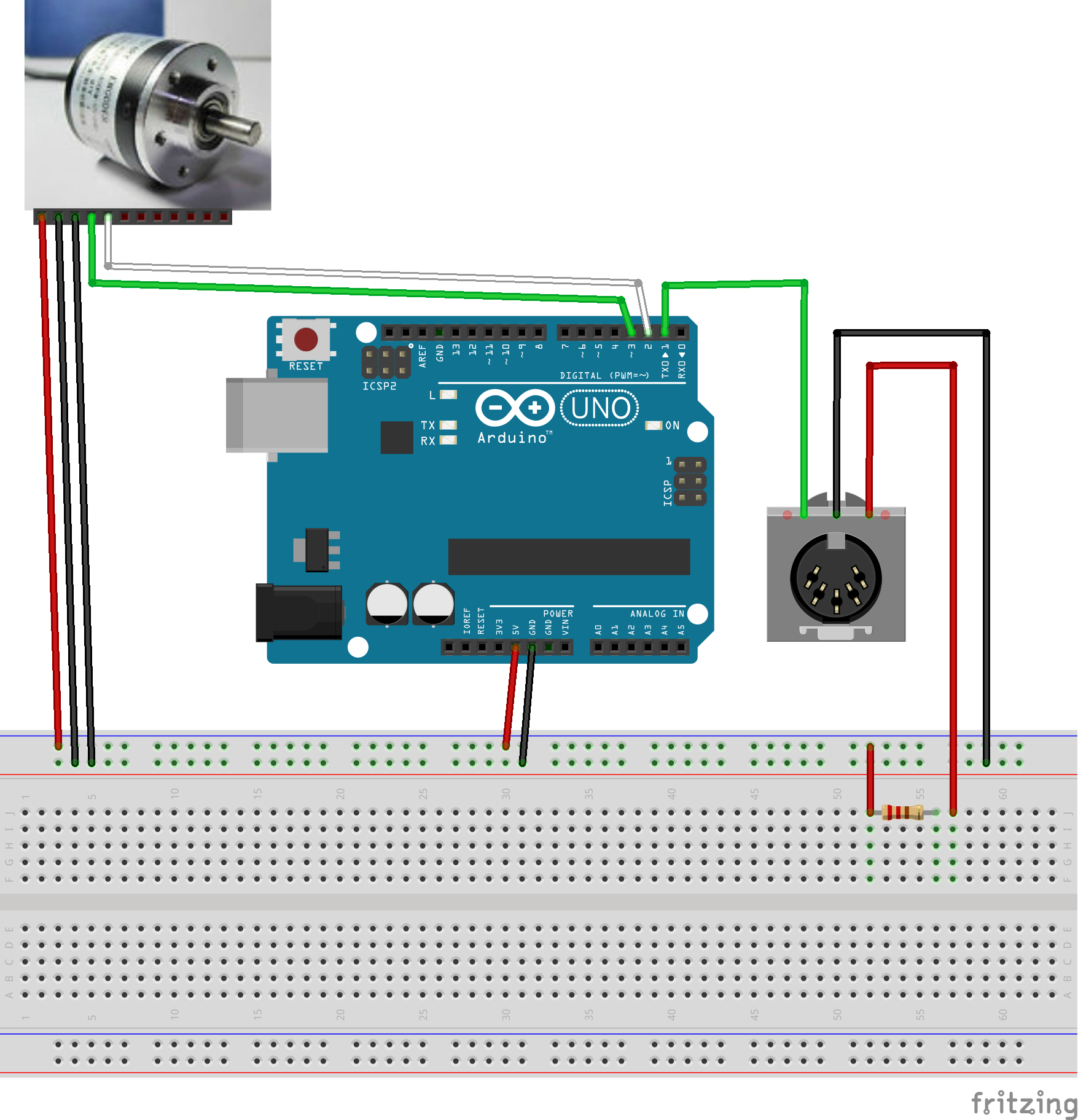
the basic circuit

It's weird. Another possibility: does the weird baud rate somehow mess with the hardware interrupts?

EDIT again: I ran mixxx in mididebug mode and span the record in one direction. This was in the log:

Debug [Controller]: "MIDI status 0xB0 (ch 1, opcode 0xB), ctrl 0x27, val 0x41" 
Debug [Controller]: "MIDI status 0xB0 (ch 1, opcode 0xB), ctrl 0x27, val 0x3F" 
Debug [Controller]: "MIDI status 0xB0 (ch 1, opcode 0xB), ctrl 0x27, val 0x41" 
Debug [Controller]: "MIDI status 0xB0 (ch 1, opcode 0xB), ctrl 0x27, val 0x3F" 
Debug [Controller]: "MIDI status 0xB0 (ch 1, opcode 0xB), ctrl 0x27, val 0x3E"
Debug [Controller]: "MIDI status 0xB0 (ch 1, opcode 0xB), ctrl 0x27, val 0x3F"
... for a while and then ...
Debug [Controller]: "MIDI status 0xB0 (ch 1, opcode 0xB), ctrl 0x27, val 0x3F" 
Debug [Controller]: "MIDI status 0xB0 (ch 1, opcode 0xB), ctrl 0x27, val 0x41" 
Debug [Controller]: "MIDI status 0xB0 (ch 1, opcode 0xB), ctrl 0x27, val 0x41"
...
Debug [Controller]: "MIDI status 0xB0 (ch 1, opcode 0xB), ctrl 0x27, val 0x41" 
Debug [Controller]: "MIDI status 0xB0 (ch 1, opcode 0xB), ctrl 0x27, val 0x3F" 
Debug [Controller]: "MIDI status 0xB0 (ch 1, opcode 0xB), ctrl 0x27, val 0x3F"

So it goes from repeating 63 with an occasional 62 to suddenly repeating 65 with an occasional 66. A velocity of 64 means the wheel isn't moving. 63 means moving counterclockwise one pulse. 65 is clockwise one pulse . Or vice versa depending on how the thing is wired.

Does that imply that the problem is in the arduino and not in the midi adapter(s)?

\$\endgroup\$
5
  • \$\begingroup\$ Please add the circuit diagram you use to connect the Arduino to the MIDI cable. How long is the cable you use? \$\endgroup\$
    – jippie
    Commented Feb 24, 2014 at 7:00
  • \$\begingroup\$ I don't have the cables in front of me, but one cable was about 12 inches. The other around 30 ,inches. The cheap USB-Midi adapters have built-in MIDI cables that are probably under 12 inches in length. \$\endgroup\$ Commented Feb 24, 2014 at 21:43
  • \$\begingroup\$ Do you have a scope to look at the wave form? Can you check the power supply voltage for the ATmega on the Arduino? \$\endgroup\$
    – jippie
    Commented Feb 24, 2014 at 21:58
  • \$\begingroup\$ @jippie I don't have a scope. Do you want me to check the voltage across 5V and ground pin? Or between specific pins on the chip itself (7 and 20; or 22 and 20)? Before posting the question, I did try a few different power supplies with the same result. USB power, 5V DC adapter, and 12V DC adapter all had more or less the same result. \$\endgroup\$ Commented Feb 24, 2014 at 22:11
  • 1
    \$\begingroup\$ How about sending a pre-programmed sequence of bytes and see if that successfully arrives at the destination. Try to rule out the encoder. Voltage across the power pins of the controller is best, bot be careful not to short anything. I guess measuring the 5V and GND pins should be fine and safe. \$\endgroup\$
    – jippie
    Commented Feb 25, 2014 at 5:56

2 Answers 2

6
\$\begingroup\$

Your baud rate is not an integer divisor of your MCU clock. The baud rate is divided from the MCU's clock. It is easy to get 9600, 19200 and other rates with an integer divisor of the clock. for example, if you have a 6.144MHz crystal, to get 19200 you need to divide by 3200.

For the odd data rates in various applications (Audio, analog video, and many others) specific crystals are used in order to get an integer divisor, for example, an NTSC circuit might have a 5.034963MHz crystal for generating the various sync signals, see

Crystal oscillator frequencies - WikiPedia

If your MCU has an internal clock generator, try adjusting it to a different value in order to get an integer divisor, otherwise, the bit error will be too high.

\$\endgroup\$
4
  • 6
    \$\begingroup\$ I just had a look and the Uno runs at 16MHz, at 16 cycles per bit for the UART 1M / 31250 = 32 so setting UBRR to 31 shouldn't give any error. While 31250 is an unusual baud rate by traditional standards it does divide into even MHz frequencies which is probably why they used it. \$\endgroup\$
    – PeterJ
    Commented Feb 24, 2014 at 12:45
  • 2
    \$\begingroup\$ UBRRn's value should be 31 (16MHz/31250) -1, an exact value which is optimal for the USART. Strange. \$\endgroup\$
    – Lior Bilia
    Commented Feb 24, 2014 at 13:14
  • \$\begingroup\$ I saw something about this in my searches. I thought it was possibly the cause of my problems, but I wasn't sure how to do the math. So, this shouldn't be a problem then? The math checks out? \$\endgroup\$ Commented Feb 24, 2014 at 21:53
  • \$\begingroup\$ The divider is optimal, with 0% error (usually the dividers introduce a small error), next I would check the USART routines, perhaps they do not support the odd baud rate. \$\endgroup\$
    – Lior Bilia
    Commented Feb 25, 2014 at 6:08
4
\$\begingroup\$

One definitive way to test is to wire your MIDI out to your MIDI in, and set up the system using the USB-serial as before, but routing it (through your 'virtual midi cable' software) to the MIDI out port on the computer. This will test to see if your USB MIDI hardware is in fact working reliably at the data rate the device works at. In my experience, many USB MIDI devices are basically designed for keyboards (which only send 3 bytes or so when a key is pressed or released) and have weird overflow problems when you transmit at the full 31.25 Kbit rate. This is also very much operating system / driver dependent.

I guess you also want to make sure that the transmitter/line driver is working. Please post a schematic of your Arduino MIDI-out circuit. What are you using as the output driver?

I'm making a lot of assumptions, but assuming the Arduino Uno at 16 MHz, 31250 bps is exactly supported (0% error) with a UBBR register value of 31, according to this: AVR UART rate calculator. This indicates to me that the bit rate of MIDI shouldn't be a problem (in fact, my understanding is that 31250 was largely chosen to be easy to work with with a 1MHz clock, unlike the teletype machine derived RS-232 rates).

Also, a dump of what messages the PC is receiving through a MIDI sniffer or monitor would be very useful in debugging.

\$\endgroup\$
10
  • \$\begingroup\$ If you wire MIDI-out to MIDI-in, wouldn't any baud rate problems associated w/ the platform at hand remain hidden, as both share the same clock?? \$\endgroup\$ Commented Feb 24, 2014 at 14:53
  • 1
    \$\begingroup\$ Well, I was more wanting to test the driver with full rate information. My experience is that some USB-MIDI cables will choke due to buffer overflows and such when connected to something that sends more data than a keyboard. \$\endgroup\$
    – Zuofu
    Commented Feb 24, 2014 at 17:35
  • \$\begingroup\$ I will try connecting MIDI in to MIDI out and get back to you. I also tried doing 31250 through serial and looking at the results in Putty. But the screen got flooded with too much stuff. I'll do it again when I get home, and save the file. And I'll try looking at the Mixxx log as well, which can be set to log midi messages. \$\endgroup\$ Commented Feb 24, 2014 at 21:51
  • \$\begingroup\$ Can you change the serial.print to print to (ascii) console the value of the encoder variable and look at it through RealTerm? Your quadrature decode setup is unusual. It is typically not a good idea to interrupt on both A and B. For example, if you interrupt on any change of A, if A==B then B leads A, if A!=B then A leads B. The way you have it written seems much more complex, I'm not gonna say it won't work, but there might be some unintended effects there. \$\endgroup\$
    – Zuofu
    Commented Feb 25, 2014 at 5:11
  • \$\begingroup\$ Also, your program logic seems sort of confused. 'lastreportedPos' is almost always 0, except if an interrupt fired in the tiny slice of time before it is assigned and the previous line setting 'encoderPos' to 0..? Also, why is lastreportedPos unsigned, while encoderPos is signed? The typical way to use an encoder is to keep track of the position (either from an index signal, if you have one, or from some arbitrary position at powerup). If you want to send a relative position, you use a delta-x like you are doing, except you do not reset the position right before... \$\endgroup\$
    – Zuofu
    Commented Feb 25, 2014 at 5:36

Your Answer

By clicking “Post Your Answer”, you agree to our terms of service and acknowledge you have read our privacy policy.

Not the answer you're looking for? Browse other questions tagged or ask your own question.