0
\$\begingroup\$

enter image description hereenter image description here
I am using optocoupler PC817 to create optical isolation between my digital signal and arduino due and arduino mega 2560 . And I am using external pull-up resistor connected with 3.3 V (to pull up digital pins of arduino due and arduino mega 2560). And output pin of optocoupler is also attached with the above mentioned 3.3V.

When no digital signal is given to the input pin of optocoupler, its output pin( collector pin, as attached with the externally pulled up pin of arduino) gives 3.3V but when the optocoupler receives digital signal its output pin gives 0V and hence pulling down the input pin of arduino which is taken as input in arduino. It works fine when I give digital signal from external power supply.

But when I give digital signal from function generator(5V at 10Hz), the output of optocoupler does not get to '0' completely rather it gives around 2.5V.

I guess it's the function generator that is causing problem. It is not providing enough current to the LED in optocoupler to glow fully. Could any one help me out how to make optocoupler work when signal is given from function generator?

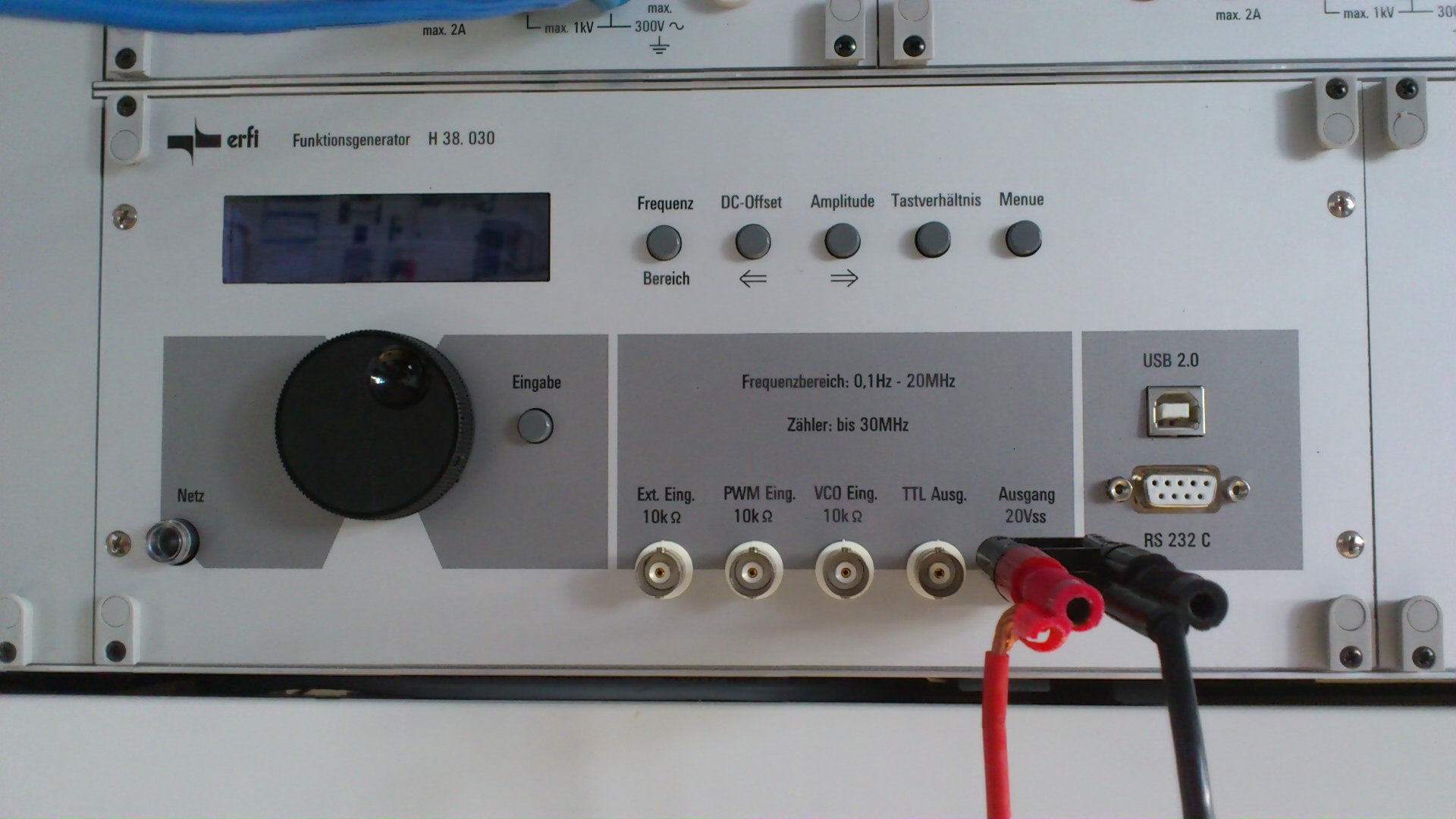
The functiongenerator I am using is shown in the picture below... It is "erfi funktionsgenerator H 38. 030"

Its german function generator and its manual or guide line book is in German...

\$\endgroup\$
6
  • \$\begingroup\$ Please add a circuit diagram for your set up. Edit your question, hit ctrl+k. \$\endgroup\$
    – jippie
    Commented Mar 1, 2014 at 19:18
  • \$\begingroup\$ How is the function generator configured (signal type, output level) and what value resistor did you use for the opto-diode and for the opto-transistor pullup? \$\endgroup\$
    – alexan_e
    Commented Mar 1, 2014 at 19:23
  • \$\begingroup\$ Also, please provide the specifications for the output impedance, voltage, and current for your function generator. What is the highest frequency you want to pass through the optocoupler? Is your generator supplying a square wave or a sine wave? \$\endgroup\$
    – Joe Hass
    Commented Mar 1, 2014 at 19:24
  • \$\begingroup\$ Signal type is Square wave. Amplitude is 5V. Minimum frequency I am testing is 10Hz and maximum I want is 30KHz... Opto-Diaode resistor is of 570 Ohm and pull-up resistor is of 20K ohm... \$\endgroup\$
    – user38026
    Commented Mar 1, 2014 at 19:34
  • \$\begingroup\$ Have you tried lowering the resistor value to .. say .. something around 200R. That should give you around 25mA. \$\endgroup\$
    – Tom L.
    Commented Mar 1, 2014 at 22:00

3 Answers 3

1
\$\begingroup\$

Use a comparator circuit to convert your "feeble" function generator signal to a decent square wave. This will be suitable for driving the opto's "LED" (via the appropriate value resistor). I'd use a fast-ish op-amp for simplicity like the AD8605 - it has a 10MHz bandwidth and is more than capable of driving an opto (given the slowness of most optos). Don't forget to add a little hysteresis - probably about 1% to prevent multiple glitches as the waveform (and noise) pass the comparator trigger point.

There may be another problem of course - your function generator may have a DC offset pot and this may be set so that the waveform output never gets low enough to turn the opto LED off.

EDIT

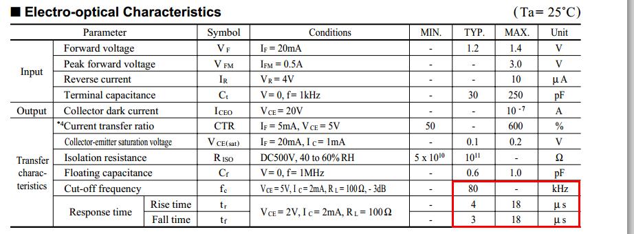
The OP has now stated that the Opto is a PC817 and that they wish to work with frequencies upto 30kHz. The Opto specified has a max rise time and fall time of 18 us and this means the opto isn't suitable and is likely to be the cause of the problem: -

enter image description here

Note that it states the cut-off frequency is 80kHz (typically) and at this frequency the output from the Opto is going to be very poor in rise time and fall time (about 4us) but it's worse if you took maximum limits into consideration. If you can live with the asymmetrical mark-space ratios and the delay then consider adding a comparator stage between opto and arduino - if you can't then choose a faster device.

\$\endgroup\$
9
  • \$\begingroup\$ Actually the problem is that, the more circuits I include the more delays I would add in the over all system. I want as minimum circuitry as required. \$\endgroup\$
    – user38026
    Commented Mar 1, 2014 at 19:45
  • \$\begingroup\$ Can I fix the problem by changing the pull-up resistor so that even If I get 1.5~1.8V when optocoupler gets digital signal from function generator, arduino still considers it as input??? \$\endgroup\$
    – user38026
    Commented Mar 1, 2014 at 19:50
  • \$\begingroup\$ The PC817 opto has a specfied rise time and fall time of 18us max - this means it won't work well at 30kHz - you need to choose a faster device. \$\endgroup\$
    – Andy aka
    Commented Mar 1, 2014 at 19:50
  • \$\begingroup\$ But the OP say the testing was done at 10 Hz. Aren't you shooting in the dark here, pretty much just guessing? \$\endgroup\$
    – Joe Hass
    Commented Mar 1, 2014 at 20:03
  • \$\begingroup\$ @JoeHass "Minimum frequency I am testing is 10Hz and maximum I want is 30KHz" - that's what the dude says in a comment. TBH he should write it in the question to make it clearer! \$\endgroup\$
    – Andy aka
    Commented Mar 1, 2014 at 20:14
1
\$\begingroup\$

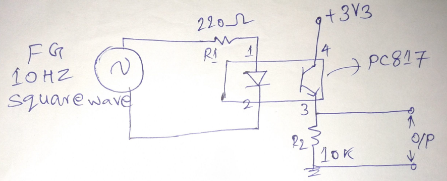
20Kohm pull up resistor mayn't let the Vce to swing near to ground try to decrease the value of Pull-up resistor such as 1Kohm or use a 10K pull down resistor and put 220E resistor for opto LED refer the schematic shown below.

If you don't get the expected output;keep your scope in DC couple mode and take the waveform across the opto LED & the output of opto and post it here. enter image description here

\$\endgroup\$
0
\$\begingroup\$

Reduce R1 to 150-200 ohm. This will increase current in led and transistor will be opened better.

\$\endgroup\$
1
  • 1
    \$\begingroup\$ This does not add very much to the existing answers. \$\endgroup\$
    – David
    Commented Nov 20, 2015 at 15:36

Your Answer

By clicking “Post Your Answer”, you agree to our terms of service and acknowledge you have read our privacy policy.

Not the answer you're looking for? Browse other questions tagged or ask your own question.