2
\$\begingroup\$

I was just wondering what the equation is to find the 555's output frequency is, when a control voltage is applied to pin 5. That would be very useful for me to know!

[Edit By OP]

So based on what Spehro Pefhany said, the equation for the output frequency (Substituting the equations for the high and low times) would be:

Formula

Where:

\$V_{Control}\$ is the control voltage

\$C \$ is the timing cap

\$V_{cc}\$ is the supply voltage

\$R_{1}\$ and \$R_{2}\$ are the timing resistors

\$f\$ is the output frequency

\$\endgroup\$
3
  • 2
    \$\begingroup\$ Are you able to understand the exponential formula (not the simpler one in the data sheet) for frequency when pin 5 is not used? \$\endgroup\$
    – Andy aka
    Commented Mar 2, 2014 at 17:24
  • \$\begingroup\$ Have a look at this collection of how-to knowledge on 555 timers. \$\endgroup\$ Commented Mar 3, 2014 at 19:45
  • 1
    \$\begingroup\$ Nick's link suggestion currently returns a 404, seems it has moved to/should be home.cogeco.ca/~rpaisley4/LM555.html - that site is packed with good info! \$\endgroup\$
    – tardate
    Commented Mar 15, 2015 at 13:21

3 Answers 3

3
\$\begingroup\$

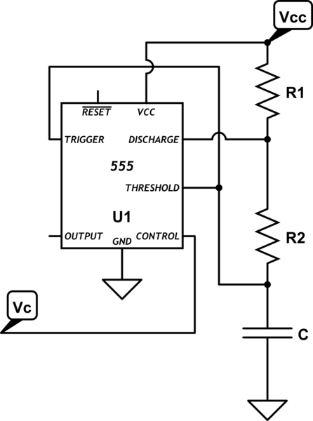
schematic

simulate this circuit – Schematic created using CircuitLab

The time when the output is high is \$ T_H = \tau_1ln(1- \$ \$V_C\over 2Vdd - Vc \$)

(it charges from \$V_C/2\$ to \$V_C\$)

The time when the output is low is \$T_L = \tau_2 ln(2)\$

(it discharges from \$V_C\$ to \$V_C/2\$)

frequency is f = \$1\over T_H + T_L\$

Where

\$ \tau_1 = (R1 + R2)\cdot C\$

\$ \tau_2 = (R2) \cdot C\$

The above ignores propagation delays and saturation voltages, so it's more accurate for low frequencies, fairly high resistance values, and a CMOS 555.

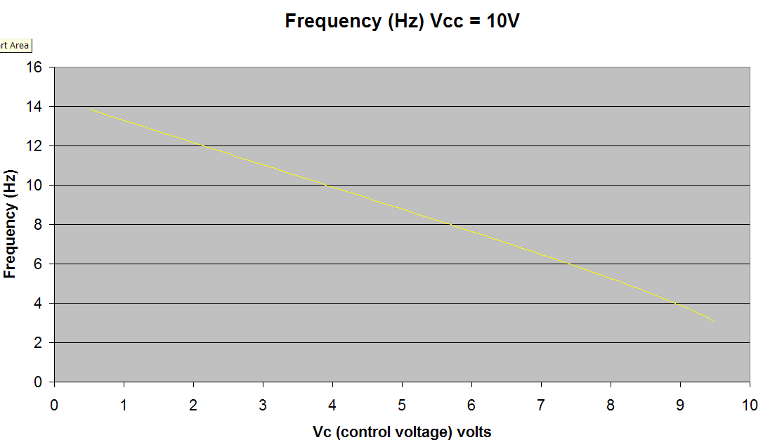
Here is an example plot with R1 = 1K, R2 = 10K, C = 10\$\mu\$F, Vcc = 10V and \$V_C\$ varied from 0.5V to 9.5V.

enter image description here

\$\endgroup\$
8
  • \$\begingroup\$ This is EXACTLY what I was looking for!! Thanks! \$\endgroup\$
    – Zack Frost
    Commented Mar 2, 2014 at 19:25
  • \$\begingroup\$ I did not know about the "tick"! \$\endgroup\$
    – Zack Frost
    Commented Mar 2, 2014 at 19:49
  • \$\begingroup\$ @Spehro something seems wrong with the formula as written for Th. The graph seems right, but if you calculate as stated the answer is wrong E.g for R1 = 1K, R2 = 10K, C = 10μF, Vcc = 10V and VC = 9.5V, chart indicates ~3Hz (correct) but calc = -5Hz. I suspect I see the error .. missed the inversion of e^-t/τ when deriving Th? \$\endgroup\$
    – tardate
    Commented Mar 15, 2015 at 17:04
  • \$\begingroup\$ @Spehro PS: I posted my calcs as another answer as too much to fit in a comment! If you agree, feel free to update you answer .. or tell me where I messed up! electronics.stackexchange.com/a/160011/52289 \$\endgroup\$
    – tardate
    Commented Mar 15, 2015 at 18:20
  • \$\begingroup\$ @tardate You're probably correct, I'll check later, thanks. \$\endgroup\$ Commented Mar 15, 2015 at 18:25
9
\$\begingroup\$

what the equation is to find the 555's output frequency is, when a control voltage is applied to pin 5

By my calculations, the accepted answer and the formula echoed in the question are wrong. I believe the correct formula for frequency when a control voltage is applied is:

\$ f = { 1 \over C \cdot (R_1 + R_2) \cdot ln({1 + { v_{cont}\over {2 \cdot ( v_{cc} - v_{cont} ) } } }) + C \cdot R_2 \cdot ln(2) } \$

To run this formula in WolframAlpha, use this link.

With constituent components:

\$ t_h = C \cdot (R_1 + R_2) \cdot ln({1 + { v_{cont}\over {2 \cdot ( v_{cc} - v_{cont} ) } } }) \$

\$ t_l = C \cdot R_2 \cdot ln(2) \$

Why am I challenging the accepted answer?

I needed to run this calculation today, tried the formula suggested ... and got really weird results (like negative frequencies, and a trend that seems inversely proportional to that expected).

The reasoning in the approved answer is sound, and the chart seems correct, but the formula seems to have suffered a transcription/transposition error specifically in relation to the calculation of \$ t_h \$.

For example, if I use the formula provided to calculate R1 = 1K, R2 = 10K, C = 10μF, Vcc = 10V and VC = 9.5V I get an answer of -5.2816 Hz (when it should be ~3Hz as the chart suggests).

I'm posting my run of the calculation from scratch here as a new answer. If Spehro, OP and all agree with my calcs, I'm happy to see the original question and accepted answer updated (I'm not a rep whore).

NB: I'm using the TI NE555 datasheet for reference as it has more internal details than others I've seen.

In astable configuration, charge discharge follows these rules (from the datasheet):

  • THRES > CONT sets output low and discharge low
  • TRIG < CONT/2 sets output high and discharge open

Conventionally when pin 5 is unused (cap to ground), CONT = VCC * 2/3 due to the three stage voltage divider.

Given the complete RC response is

\$ v_t = v_\infty + (v_0 - v_\infty)e^{-t/\tau} \$

Then when pin 5 CONT has a voltage \$ v_{cont} \$ applied, our full charge boundaries are defined by:

\$ v_\infty = v_{cc} \$

\$ v_t = v_{cont} \$

\$ v_0 = {v_{cont}\over 2} \$

So plugging that back into the complete response formula:

\$ v_{cont} = v_{cc} + ({v_{cont}\over 2} - v_{cc})e^{-t/\tau} \$

Simplifying and re-arranging to derive a formula for \$ t = t_h \$:

\$ v_{cont} - v_{cc} = ({v_{cont}\over 2} - v_{cc})e^{-t/\tau} \$

\$ {v_{cont} - v_{cc} \over {v_{cont}\over 2} - v_{cc}} = e^{-t/\tau} = {1 \over e^{t/\tau}} \$

NB: I think this is the missing step. If we don't invert here, we derive the formula as currently listed in the Q & A.

\$ {{v_{cont}\over 2} - v_{cc} \over v_{cont} - v_{cc} } = e^{t/\tau} \$

\$ {1 + { v_{cont}\over {2 ( v_{cc} - v_{cont} ) } } } = e^{t/\tau} \$

\$ ln({1 + { v_{cont}\over {2 ( v_{cc} - v_{cont} ) } } }) = t/\tau \$

\$ t = \tau ln({1 + { v_{cont}\over {2 ( v_{cc} - v_{cont} ) } } }) \$

So I'm concluding the formula for \$ t_h \$ is actually:

\$ t_h = C \cdot (R_1 + R_2) \cdot ln({1 + { v_{cont}\over {2 \cdot ( v_{cc} - v_{cont} ) } } }) \$

So if I go back and revise the calculation of R1 = 1K, R2 = 10K, C = 10μF, Vcc = 10V and VC = 9.5V I now get an answer of 3.0491 Hz. That's much more reasonable, and matches Spehro's chart.

\$\endgroup\$
2
  • 6
    \$\begingroup\$ +1 Read meta. Came here :-). This is real engineering, even if it does relate to the Arduino of the IC timer world :-) :-) :-) :-) . \$\endgroup\$
    – Russell McMahon
    Commented Mar 17, 2015 at 6:48
  • \$\begingroup\$ haha, I'm stealing Russell's idea. From now on, I think I'll just call them 555duinos;-) \$\endgroup\$
    – tardate
    Commented Mar 26, 2015 at 17:49
5
\$\begingroup\$

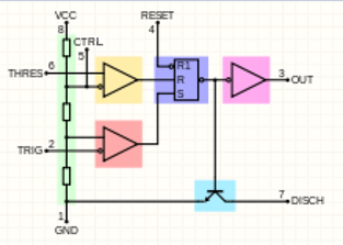
If you mean in A-stable multivariate circuit of 555, considering the block diagram of IC:

wikipedia:555 timer ic

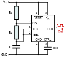
and the circuit of A-stable:

enter image description here

Voltage of C changes periodically between \$V_{CC}/3\$ and \$2V_{CC}/3\$ which are the reference voltages of upper op-amp and lower op-amp.

So if you change the reference voltage of upper op-amp by \$CTRL\$, then voltage of C changes between \$CTRL = (V_{Ctrl})\$ and \$V_{Ctrl}/2\$. (Provided of course that the source impedance driving the CTRL pin is much much lower than the impedance looking into the CTRL pin. If the source impedance is within an order of magnitude of the input impedance at the CTRL pin then this would not hold and a more complex analysis required that factors in the source impedance).

as the charging evaluation of capacitor is: \$V_{CC} - (V_{CC} - V_{Ctrl}/2) e^{-t/\tau} = V_{Ctrl}\$ and \$\tau = C(R_1+R_2)\$

so the high time will be \$t_H = -\tau ln[2(V_{Ctrl}-V_{CC})/V_{Ctrl})]\$

And for low time (\$t_L\$) the \$\tau\$ changes to \$CR_2\$. As you know the frequency is \$1/(t_H + t_L)\$

\$\endgroup\$
5
  • 2
    \$\begingroup\$ Maybe change "CONT" to "CTRL" or better still \$V_{CTRL}\$ - YOU CAN ALSO USE "dfrac{Vcc}{3}" to replace Vcc/3 - it just looks a tad better dude but +1 for succinct explanation. \$\endgroup\$
    – Andy aka
    Commented Mar 2, 2014 at 18:43
  • 1
    \$\begingroup\$ Take a look at your internal structure picture for the 555. The lower op-amp threshold voltage does not stay at Vcc/3 if the CTRL pin is used. If the source impedance of the CTRL driver is low then the lower opamp threshold will become CTRL/2 due to lower two internal divider resistors. If the source impedance driving the CTRL pin is higher (i.e. starting to get to within an order of magnitude of the internal three resistor divider values) then the source impedance needs to be considered in the calculation of the actual opamp thresholds - both upper and lower. \$\endgroup\$ Commented Mar 2, 2014 at 19:08
  • 1
    \$\begingroup\$ I think there's a problem with those equations. The capacitor charges/discharges between Vc and Vc/2. \$\endgroup\$ Commented Mar 2, 2014 at 19:16
  • \$\begingroup\$ @MichaelKaras and Spehro_Pefhany, You are right. I'll correct the equations. \$\endgroup\$ Commented Mar 2, 2014 at 19:26
  • \$\begingroup\$ I'm changing the picture and text to change everything over to CTRL. \$\endgroup\$ Commented Mar 3, 2014 at 6:30

Your Answer

By clicking “Post Your Answer”, you agree to our terms of service and acknowledge you have read our privacy policy.

Not the answer you're looking for? Browse other questions tagged or ask your own question.