0
\$\begingroup\$

I am using the IRF9321 P channel MOSFET for controlling my BLDC motor. The MOSFET is driven via a transistor which in turn is run by a freescale controller(3.3V pin). Now, when turning it on, it works fine. But, when turning it off its a disaster with the MOSFET taking almost 5ms to come to '0' Volts.

My circuit is shown below.
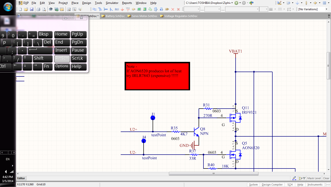
MOSFET circuit

I have been through the datasheet and it says turn off delay time is 180nSecs (approx .1uSecs).

Am I missing something?

\$\endgroup\$
3
  • \$\begingroup\$ I was expecting in micro-seconds, but 5msecs is really bad. Also, will having a diode(schottky) as a Baker clamp reduce the discharge. I have a 0603 reistor. Any suggestions for the Schottky. \$\endgroup\$
    – Board-Man
    Commented Mar 5, 2014 at 17:01
  • \$\begingroup\$ What load have you got connected? \$\endgroup\$
    – Andy aka
    Commented Mar 5, 2014 at 17:54
  • \$\begingroup\$ Hello Sir, i have got no load.Its just to observe if the voltage comes out fine or not> I intend to connect a BLDC Motor to it. Vinod. \$\endgroup\$
    – Board-Man
    Commented Mar 5, 2014 at 19:56

2 Answers 2

0
\$\begingroup\$

I presume you mean 5usec, not 5msec. If it is really 5msec, disregard the below and check for a bad (open) resistor, or perhaps one that is 270K not 270 ohms.

That's not far off what you'd expect discharging the gate charge, which could be relatively large (tens of nanocoulombs) with a 270 ohm resistor.

The MOSFET will only switch in 180nsec if you actually change the gate-to-source voltage fast.

To get it to switch quickly, you could use a gate driver capable of amperes of current such as the MCP1406/1407 which will quickly discharge the gate charge.

\$\endgroup\$
11
  • \$\begingroup\$ Hello Spehro, Thank u for ur input.Indeed its 5mSecs and not 5uSecs. The drain , I am connecting to the ADC via a voltage divider n/w. The resistors on this line have been removed(making it open). But, I don't see it interfering with the turning off time of MOSFET though. \$\endgroup\$
    – Board-Man
    Commented Mar 5, 2014 at 17:13
  • \$\begingroup\$ No 270R resistor? \$\endgroup\$ Commented Mar 5, 2014 at 17:22
  • \$\begingroup\$ Hello Sir, I have the 270R. Sorry for confusing u. I experimented with both 270R and 10K as well. in both case , surprisingly, its 5msecs. Also, in the base of the transistor I am using almost 4.7K. Do you think that cld be the thing sir. \$\endgroup\$
    – Board-Man
    Commented Mar 5, 2014 at 17:23
  • \$\begingroup\$ Base resistor I don't think will make a difference in terms of milliseconds. \$\endgroup\$ Commented Mar 5, 2014 at 18:02
  • \$\begingroup\$ Sir, do u think long tracks to the gate will make this happen. Vinod. \$\endgroup\$
    – Board-Man
    Commented Mar 5, 2014 at 18:03
1
\$\begingroup\$

I have got no load.Its just to observe if the voltage comes out fine or not> I intend to connect a BLDC Motor to it. Vinod.

Without a load the time delay in switching-off may easily be several milli seconds. Are you operating the two MOSFETs independently - what I mean to say is that if you switched them both in strict time sequence, does the problem also "go-way"?

\$\endgroup\$
7
  • \$\begingroup\$ hello sir, Thank u for ur response. I did not test it that way. The 2 MOSFETs are turned on independently(never together). But never did i connect a load to it so I will connect a load and test it. I guess its becos of the no load the 5msec delay in discharge. thank u sir \$\endgroup\$
    – Board-Man
    Commented Mar 5, 2014 at 21:36
  • \$\begingroup\$ Sir, i will link up a strip LED or something else and test it. i guess it shld behave more like 5uSecs or so decal(which I was expecting in the first place) Thank u sir :) \$\endgroup\$
    – Board-Man
    Commented Mar 5, 2014 at 21:45
  • \$\begingroup\$ I hope so - good luck \$\endgroup\$
    – Andy aka
    Commented Mar 5, 2014 at 21:50
  • \$\begingroup\$ Hello Sir, I just toggled the pin with a 10msecs timer(just 1 MOSFET,not both). Again its on no load and the decay is same as before (almost 5 msecs). SO, I guess its because of no load. Sir, when u say switch them in strict time sequence, what do you mean - "Turn ON Q1 for t1 with Q2 off" and vice versa or do you suggest turning them both on at the same time(in that case, it will sing a lot of current, I suspect). Vinod. \$\endgroup\$
    – Board-Man
    Commented Mar 6, 2014 at 4:11
  • \$\begingroup\$ Switch the top FET on (bottom off of course), then switch top off and as soon as this is off (maybe 50 nano seconds later) turn the bottom one on. You should see about a 1us or less decay. \$\endgroup\$
    – Andy aka
    Commented Mar 6, 2014 at 8:12

Your Answer

By clicking “Post Your Answer”, you agree to our terms of service and acknowledge you have read our privacy policy.

Not the answer you're looking for? Browse other questions tagged or ask your own question.