I’m building a bench power supply based on two LM317 with the following specs:
- Input: 127VAC (from mains)
- Output: adjustable from 1.25VDC to 15VDC
- Current: limit adjustable from 100mA to 1.5A
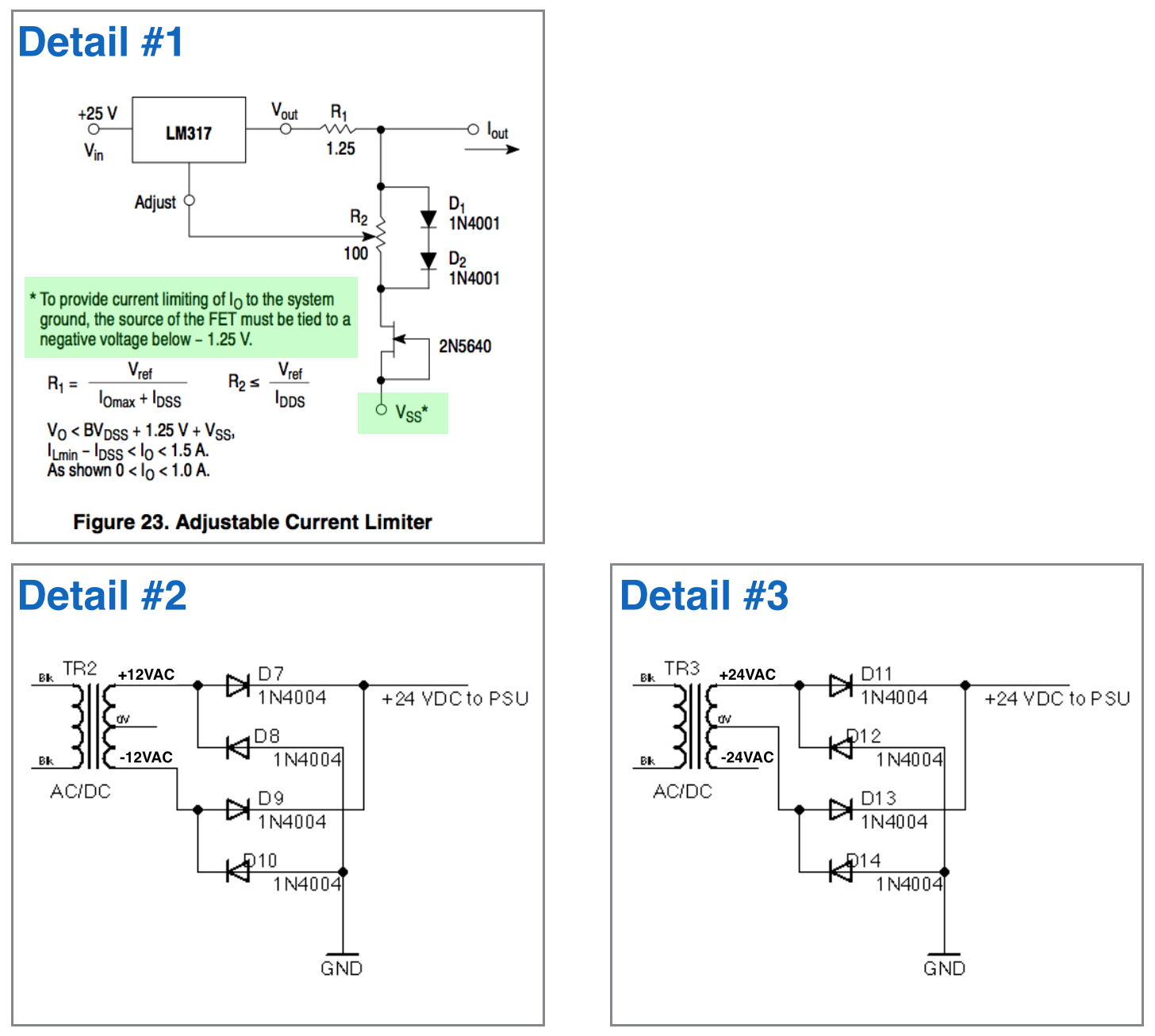
In the LM317 datasheet from On Semiconductors there is a reference for the “current regulator” circuit that requires a negative voltage (below -1.25V) in the FET (detail #1 in the figure).
Since my power supply is not handling negative voltages I was wondering on using a 24VAC center tapped transformer (127VAC to 12-0-12) ignoring the center tap to power the whole circuit (detail #2 in the figure).
So, my question is how to derive the negative voltage necessary for the FET?
Also, If I decided to use the center tap of the transformer, changing it to a 48VAC one (127VAC to 24-0-24), I’ll use the full rectifier bridge between +24VAC a 0VAC and I’ll try to extract the negative from the -24VAC of the trafo. Since I only need something around -1.5V isn’t that a waste of cooper on the trafo (detail #3 in the figure)?
What is the best approach to power the power supply and also provide the necessary negative voltage for the current regulator circuit?


