1
\$\begingroup\$

I recently bought a ZYBO FPGA board only to find out that there are exactly six regular single-ended GPIO lines wired to the FPGA. In contrast to that, 18 differential lines are available. The board's reference manual says that single-ended communication over the differential lines will work, but has "significant crosstalk". Grounding one line of the differential pair is suggested in this case, but this will obviously negate the whole purpose of having more single-ended IO lines.

So, what exactly is "significant" crosstalk? How fast would I be able to communicate (single-ended)? Would high-speed I2C work well? 2mbit SPI? What about a 25 MHz parallel data transfer? Can anything else be done to avoid or correct for crosstalk?

\$\endgroup\$

3 Answers 3

1
\$\begingroup\$

Although the lines are routed as differential pairs, it's not necessarily a killer to your kind of application. The amount of crosstalk is actually still likely to be quite small, as diffpairs are often routed closer to the groundplane than to each other. It's not like they are a twisted wire with no shield, where the signals are effectively much better coupled to each other. And the traces are likely to be relatively short I imagine (if you are contemplating parallel transmission).

I would suggest you could happily set up a 25MHz parallel bus, with a series-terminated clock to signal the device at the far end to latch the data. Drive the data on one edge, latch it on the opposite edge, you'll have 20ns of time for crosstalk and reflections to settle out). You could drive the negative side of the clock driver to '0' and place it away from the databus to keep that signal as clean as possible. It doesn't sound that different from how we used to route asynchronous SRAM databusses (all the wires run very close together with an edge triggered write-enable line) and that used to work fine :)

\$\endgroup\$
6
\$\begingroup\$

The wires in the differential pairs will be routed very close to each other, allowing signals from one wire to couple onto the adjacent wire. Most of the crosstalk is likely to be capacitive. Think of the two wires as plates in a capacitor. A sudden change in one wire will 'leak' onto the other one. Coupling like this is frequency-dependent. DC will not couple at all. Slow edges may couple a little bit. Very fast edges can couple very significantly. If you put a square wave with very fast edges on one wire, the adjacent wire will get sharp positive and negative going edges, followed by exponentially decaying slopes. The positive peaks correspond to the rising edge of the square wave, the negative peaks correspond to the falling edge.

If you are forced to use differential I/O as single-ended I/O, there are a few considerations. If the overall trace length is short, the effects may be so small they can be ignored. If the trace is long, then you might need to do something mitigate the crosstalk. One easy solution is to only use one wire out of each pair. The other wire can be driven to ground, or the two can be driven at the same logic level. This reduces the number of available I/O by a factor of 2, however. Another possibility is to decrease the slew rate of the output I/O pins. Xilinx FPGAs have several selections for drive strength and slew rate. Turn the slew rate to the lowest setting, quietio. Also try turning down the drive strength. You can also try turning on the 50 ohm source impedance as this will limit how much current can flow out of the pin. Setting the 50 ohm source impedance should also limit reflections off of the FPGA I/O pins, as signals in an unmatched system can bounce around for some time, requiring more time to stabilize.

It's hard to say how fast you would be able to run without significantly more information about what you're trying to do. Unfortunately, I am not familiar enough with the board to be able to give you any estimates. It looks like the traces could be pretty short, though.

To get an idea of how much crosstalk you can get on a pair, set the FPGA to hold one at a constant level (GND or VDD) and toggle the other one at a few MHz. Set the slew rate to fast on the IO pin. Then connect a scope to the 'victim' pin and measure the height of the peaks. If it's much less than VDD, then it might not cause any problems.

\$\endgroup\$
4
\$\begingroup\$

If you have a single wire and a return (ground) and transmitted data, at any point along the length of the wire the average electric field will be from the data wire and ground - in simple terms, if the data was 5V p-p, the electric field would be half of this value. This is not right at the wire but at some short distance from the pair.

On a differentially driven pair of wires the signals are antiphase meaning if one is at 5V, the other will be at -5V - the net electric field is zero over the whole length of the cable except when up close to one wire or the other.

It's the same with regular antiphase logic levels - you can imagine that 2.5V is the midpoint - one wire is at 2.5V above the mid-point whilst the other is 2.5V below the midpoint.

So, if a differentially driven wire doesn't generate a significant electric field then there is no cross-talk. That's the simple version. There is also the magnetic field to consider but, because current is travelling up one wire and in the reverse on the other AND the two wires have equal geometries, the net magnetic field at some shortish distance is zero theoretically.

So, what exactly is "significant" crosstalk? How fast would I be able to communicate? Would high-speed I2C work well? 2mbit SPI? What about a 25 MHz parallel data transfer? Can anything else be done to avoid or correct for crosstalk?

  1. Hopefully I've answered that but it does get more complex as data speed rises because you need balanced terminations.
  2. Over screened twisted pair I have designed circuits that work over 35 metres at about 400Mbpsec. There are plenty faster than that but I thought I'd share my personal work as an example.
  3. I2C requires pull-ups and I'm not sure that this would work due to cable capacitance problems - you won't get as far is my guess. SPI is fine - I've done 2Mbpsec over 15m using balanced cable techniques.
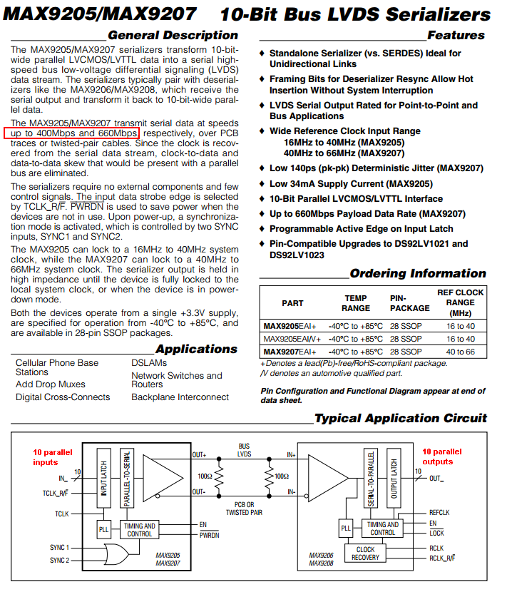
  4. 25Mbpsec parallel data becomes a problem when delay times between one pair and the next cause the data to be misread at the receiver. I tend to use chipsets like the MAX9205 - it is a 10 bit wide data serializer good for 600Mbpsec: -

enter image description here

You can get the same chip from TI but it has a different number and they are interchangeable.

\$\endgroup\$
3
  • \$\begingroup\$ Thanks so far, it did make things a lot clearer. I'll look into the MAX as well. However what I meant to ask was in how far single-ended communication would be affected when using lines (or wires, generally) laid our for differential signaling. At the moment, my concern is purely about the lanes on the board from the FPGA up to the (Pmod) connector. The wires won't be that long either; Basically it's about a breadboard-sized experiment with a OV7670 camera clocking out 8-bit data at 25 MHz - I'm running out of GPIOs. \$\endgroup\$
    – sunside
    Commented Mar 7, 2014 at 17:05
  • \$\begingroup\$ How long is a piece of string. I've sent single-ended 40Mbpsec down very good coax at a distance of 350 metres. There is nothing inherently wrong about non-differential signalling but, in the presence of interence it is many times more susceptible but "many times" might mean twice or ten times - it's job dependent and cable dependent and speed dependent and protocol dependent. \$\endgroup\$
    – Andy aka
    Commented Mar 7, 2014 at 17:15
  • 1
    \$\begingroup\$ There are things you can do to minimize noise and cross talk problems. One way I used to do was using an old 80 wire IDE cable to connect my signals to my FPGA board. It takes some time to make the special connectors, but then you have a cable with GND between each signal which is pretty helpful if you are running many signals at relatively high speed. For the PMOD, I think 25MHz should be OK, the problem is the number of wires and how you connect them to the FPGA. \$\endgroup\$
    – FarhadA
    Commented Mar 8, 2014 at 7:05

Your Answer

By clicking “Post Your Answer”, you agree to our terms of service and acknowledge you have read our privacy policy.

Not the answer you're looking for? Browse other questions tagged or ask your own question.