Is any of the the two following schematics for Line input? Or is it for the amplified signal that goes to the speakers?
 ( source )
 ( source )
Is any of the the two following schematics for Line input? Or is it for the amplified signal that goes to the speakers?
 ( source )
 ( source )
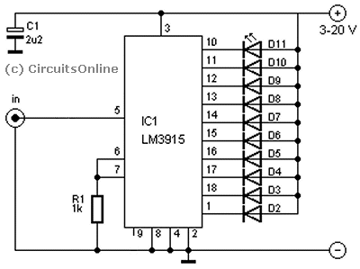
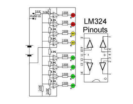
The LM324 schematic you provided is just a mirror copy of bare LM391x internals - it's just a simple op-amp based ADC; also, it doesn't provide the exact voltages nor application, so while it can be used to measure something, it's hard to say exactly what. I'll thus ignore it and just focus on LM391x chip here.
The LM3915 schematic you provided is simply wrong to be used as VU meter for many, many reasons. Let's start with that magic "3-20V" there (probably stolen from datasheet's reference implementation). In reality, the datasheet for LM3915 gives a broader V+ range - 3V to 25V. Also, it's arguable whether it's good to use VLED = V+ (as shown on the diagram) for higher V+ values; quote from the datasheet:
VLED must be kept below 7V or dropping resistor should be used to limit IC power dissipation.
That means that with e.g. 20V supply both on V+ and VLED, it's possible to burn the chip due to overheating it. Also, the same datasheet says explicitly:
3V > VLED > V+
and it's also stated that V+ has to be about 2V-3V higher than the higest voltage needed to be measured on SIG. As such, it seems that it's best to supply VLED as low as possible (e.g. 3V or 5V), and V+ that's possibly higher, if you need to measure signals with higher amplitude.
Now, about the VU meter itself.
First thing is, VU meters should be fed with a signal with a known properties (reference hi/low voltages), strictly speaking with a signal whose 0 dB (0 VU) is referenced as +4 dBu; there's no upper boundary on generic amplified signal (depends on the exact amplifier/speakers), so you can easily burn the chip's input's op-amps. By using non-line signal you're feeding the chip with an input that's usually either too weak (headphones) or too strong (speakers) for it. It follows that you should use line levels for VU meters whenever possible.
Secondly, VU meters should have a known rise/fall times and overshoot - so there's an integrator needed for the signal used to feed digital measurement chips (analog VU meters didn't need those due to the way the inductor/indicator worked/lagged). At page 14 of LM3916's datasheet you can find one such application.
Thirdly, note that for VU-meters you should use LM3916 - LM3914 is linear-scaled, LM3915 is log-scaled, LM3916 is VU-meter-scaled, which is what you actually seek.
BTW, in case you're talking about professional VU-meter, set for its voltages: to feed a non-professional line level (-10 dBV) to a professional line level VU-meter (+4dBu) you simply have to amplify the signal 4x (eg with op-amp amplifier) - it so happens that +4 dBu is 3.886x -10 dBV... assuming 4x gives you +/-5% accuracy, about the one you have in most of your parts anyway.
Also, remember (I've already mentioned it earlier) that LM391x won't measure signals with voltages too close to its supply voltages (especially the hi voltage requires a bit of space) - but for line levels that's shouldn't be a problem anyway.
Finally:
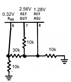
A little known fact for LM391x ADCs is that if you connect the high reference voltage (Rhi pin) directly to e.g. line level RMS voltage (for consumer audio it's −10 dBV, ie. 0.316V ~1/3V, see wiki link for more precise values; note that this won't be a VU-meter, just a simple volume meter scaled to mimic VU-meters) you'll get the scale as needed for line-level signal. This may require a bit of creativity if you want to use the internal ADC's voltage reference, because you still need to use REF OUT/REF ADJ pins to provide a valid LED current (see page 8 of the datasheet) - but it certainly can be done. If my memory serves me well, it went like this:  .
.
see:
http://www.ti.com.cn/cn/lit/ds/symlink/lm3916.pdf