1
\$\begingroup\$

I want to power four independent DC motors of a rover with arduino. Besides the voltage (6.0V) I don't have any other information about the motors.

I decided to make the rover change direction like a tank, meaning that each side's motors (right side and left side) have the same speed, but right side has different speed than left side. I also intent to use one or two L293B or simmilar chips.

I have thought of several ways of creating the circuit:

Case A: Four PWM pins of arduino, each one for controlling an induvidual motor. This means that two L293B chips are required:

  • PWM_front_left and PWM_front_right connected to the first L293B

  • PWM_back_left and PWM_back_right connected to the second L293B

Case B: Two PWM pins of arduino, each one splitting

  • PWM_left splits to PWM_front_left and PWM_back_left
  • PWM_right splits to PWM_front_right and PWM_back_right

Each one controls an induvidual motor. This means that two L293B chips are required.

Case C: Two PWM pins of arduino, each one connected to left channel and right channel of just one L293B. Two motors will be linked to the left channel and two motors will be linked to the right channel.

Are there any advantages or dissadvantages for each one of these cases?

Also, I would like to ask something about the logic pins. For each channel except of the PWM, two logic pins are required:

  • Pin_A (1) and Pin_B (0) for clockwise
  • Pin_A (0) and Pin_B (1) for anticlockwise

Since everytime B = NOT(A), instead of using two logic pins, I want to use one logic pin splitting in two parts. The first part is connected directly to the L293B. The second part passes through a hex inverter, exits as an NOT(A) and is been connected to the L293B. Is that possible to work?

\$\endgroup\$

1 Answer 1

4
\$\begingroup\$

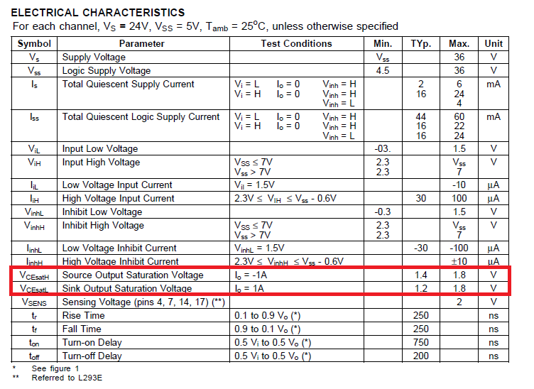
The major disadvantage in your choices/options is the L293 chip itself. It and it's cousins (SN754410 and L298) are likely very poor for what you might be trying to do. Certainly they can switch with PWM very well but the inefficiencies of the output transistors render them nearly useless on low voltage, high current applications. Take a look at this: -

enter image description here

Highlighted in red are the areas of concern. This is what it means - when a transistor is turned hard on and conducting 1A, it will "lose" about 1.3V in the process. For a H bridge, two transistors are needed and therefore your motor receives battery voltage minus 2.6V when being driven.

So if you have a 6V battery and 6 volt motors the maximum voltage (typically) that you can put on your motor is 3.4V. Worst case 2.4V. There are much better devices than these such as the DRV8833. It uses MOSFETs and has a combined on-resistance in a full H bridge of 0.36 ohms - this means at 1A being drawn, the voltage "lost" is 0.36 volts. There are even more powerful devices too.

On your main question, I'd drive all four motors independently from separate PWM channels.

\$\endgroup\$
4
  • \$\begingroup\$ Thank you for your usefull reply, I'll try to find more efficient ICs. Just one more question based on your suggestion; if I use four PWM pins plus four logic pins, is it possible to approach or even exceed the limit of 200mA? (maximum total current for ATMega 328 chips). Can I simply insert a current meter between each connected pins of arduino and motor driver in order to read the current value? Thank you. \$\endgroup\$ Commented Mar 25, 2014 at 20:44
  • \$\begingroup\$ @user3060854 I'm not sure what you mean - PWM outputs pins can be used as IO pins (on a lot of devices) and the current taken by the target chip (via its inputs) will be tiny and not 200mA. Maybe I'm misinterpreting what you mean? \$\endgroup\$
    – Andy aka
    Commented Mar 25, 2014 at 21:36
  • \$\begingroup\$ I copy from ruggedcircuits.com/10-ways-to-destroy-an-arduino . "... Configure at least 10 I/O pins to be high and draw 20mA from each one (for example, by lighting 10 LED’s). You have now exceeded the total supply current rating for the microcontroller and it will be damaged..." \$\endgroup\$ Commented Mar 25, 2014 at 22:52
  • \$\begingroup\$ Driving PWM into a logic gate input doesn't draw even 100uA. \$\endgroup\$
    – Andy aka
    Commented Mar 25, 2014 at 23:06

Your Answer

By clicking “Post Your Answer”, you agree to our terms of service and acknowledge you have read our privacy policy.

Not the answer you're looking for? Browse other questions tagged or ask your own question.