4
\$\begingroup\$

I've been fiddling around with a brushed DC motor, a 2N2222 and an arduino's PWM to get different speeds out of my motor. Now, based on a video tutorial I watched on youtube, It was recommended to put a 1k Ohm resitor between the PWM pin and the base, apparently to protect the arduino in case the transistor screwed up. I did what I was told to do, following this schematic (My power supply is 1.5V and R1 is 1K, not 220)My power supply is 1.5V and R1 is 1K
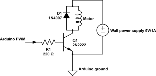
But the motor would not turn when the microcontroller pin would output 5V ( full duty). So I figured, ights, let me not mess around with my arduino in case that was the problem, so I connected the base, throught the 1k resistor, to the same 1.5V powering the motor...still nothing...put a new 1k resistor...still nothing...so I romoved the 1k Ohm resistor and plugged my base straight to the 1.5v source and the motor started turning.

Can someone please explain to me why that is? From what I've been reading, isn't the voltage at the base what determines the current flowing from the collector to the emmiter? -_- <-- Confused face

\$\endgroup\$
4
  • \$\begingroup\$ Are you sure you have the transistor wiring correct? \$\endgroup\$
    – markrages
    Commented Mar 27, 2014 at 4:41
  • \$\begingroup\$ Is the motor powered by 9 V or 1.5 V? \$\endgroup\$
    – markrages
    Commented Mar 27, 2014 at 4:41
  • 3
    \$\begingroup\$ A BJT is a "Current controlled" device, while a FET is a "voltage controlled" device. Reducing the base current by adding the resistor will reduce the emitter current. \$\endgroup\$ Commented Mar 27, 2014 at 5:43
  • \$\begingroup\$ In addition to Ignacio's answer, I would like to recommand this web-site to learn "How to use a transistor as a switch": Using Transistor as a Switch myself learnt that how to use a transistor as a switch by this web-page. \$\endgroup\$
    – Roh
    Commented Mar 27, 2014 at 7:18

3 Answers 3

13
\$\begingroup\$

The motor needs a certain amount of current in order to turn. How much current is allowed to pass through the transistor from collector to emitter, and hence through the motor, is controlled by the current passing through the transistor from base to emitter times the transistor's current gain, known as "hfe". The base resistor reduced this current to too low a value to allow the motor to turn even when amplified by the transistor. Use what you know about the motor's required current, the voltage across the transistor from base to emitter during saturation, the voltage from MCU pin to emitter, and the transistor's hfe to calculate the correct maximum value of resistor to use. E.g.:

300mA (Imotor) / 70A/A (hfe) = 4.2mA
(5V (VMCU) - 0.7V (VBE(SAT)) )/4.2mA = 1.024 kohm

Note that the motor voltage supply is not involved in these calculations, but it still must be high enough after subtracting the voltage from collector to emitter as per motor specifications.

\$\endgroup\$
1
  • 2
    \$\begingroup\$ Using a gain of 70 in the calculations will result in a base current that will not saturate the transistor (which is wanted when using the transistor as a switch) and will result in increased collector-emiiter voltage drop. The rule of thumb in order to saturate the transistor is to drive the base with a current of about 1/10 to 1/20 of the output current. The 2N2222 datasheet saturation voltages are given for a gain of 10. \$\endgroup\$
    – alexan_e
    Commented Mar 27, 2014 at 8:03
1
\$\begingroup\$

As with any NPN transistor, you have to limit the current at the base of your 2N2222, R1 is thus required, because NPN transistors are current operated parts (like LEDs).

When using an NPN transistor as a switch you want to use it in saturated mode, because it minimizes the voltage drop at the collector (cf. V_CE(sat)). For that you have to limit the current at the base to 1/10th of I_C, i.e. the current you want to drive your motor with.

Otherwise, without saturation, your transistor might get too hot/yield a too high voltage drop.

Note that a GPIO pin on your Arduino (ATmega328p) can only supply up to 20 mA. Thus, you are limited to 200 mA for your motor. Which might be insufficient.

When computing the value R1 you have to account for the voltage drop at the base (i.e. V_BE(sat)) and the voltage drop at the GPIO pin (at 20 mA, cf. V_OH vs. output current figures in the ATmega328p datasheet).

See also the - say - Onsemi 2N2222A datasheet for V_CE(sat) and V_BE(sat) figures.

An alternative to using an NPN transistor to switch your motor is using a logic-level MOSFET instead. In contrast to an NPN transistor, it's voltage controlled, thus it's more energy efficient. Also, with a MOSFET, you can switch much higher loads with the small current that is available at a GPIO pin.

\$\endgroup\$
2
0
\$\begingroup\$

I'm going to go out on a limb and assume that when you plugged in the base of the transistor to the 1.5V power source, you actually plugged it in across the motor. This would explain why the behavior was as you described.

Assuming that your implementation of the circuit was correct, and the transistor isn't backwards (it gets me all the time; it's worth double checking), the problem with this circuit it almost certainly the voltage of your power source. The transistor will chop off about 0.6V in the base to emitter junction, and probably closer to 0.8V between the collector and the emitter, depending on how saturated it is. 5V through 1K will give 5 mA, which with an hfe of about 100 (fairly standard) gives a maximum 500 mA of current through the collector.

This should be enough for a small toy motor, but you won't get 500 mA through a motor with a 1.5V-0.8V = 0.7V power supply, especially if it's just a battery or two. Like markrages suggested in the comments, you ought to be considering a power source more like your diagram, 9V. 5V would be a minimum, I'd say, or maybe 3V.

The 1K resistor is important, not because it protects your Arduino from feedback (though there's that too), but because it prevents it from shorting its 5V through the transistor, which could burn one thing or the other out (though the current supplied by an Arduino is limited, I think less than 100 mA). You should definitely use it always.

Finally, depending on how you power the Arduino, you could share its power source with the motor. If you're powering it from the barrel jack, I'm 80% certain that you can connect directly to that power supply using the Vin socket that is next to the 5V and 3.3V and all them (I'm imagining an Uno). This line won't be going through any regulating (again, 80% sure), so you wouldn't have to worry about overtaxing the Arduino's components. Conversely, you could get a decent power supply and power the motor and the Arduino with it by doing the reverse, and connecting the Arduino's Vin pin to the supply's voltage like it's intended to be...

Good luck; hope that helps.

\$\endgroup\$

Your Answer

By clicking “Post Your Answer”, you agree to our terms of service and acknowledge you have read our privacy policy.

Not the answer you're looking for? Browse other questions tagged or ask your own question.