2
\$\begingroup\$

I am new to Eagle and trying to wire up a schematic. I have an IC and the first basic task I'm doing is connecting ground pins to a GND symbol. Here is what I tried with the error:
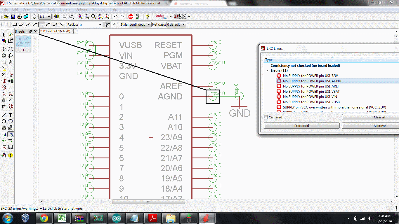
The error with what I tried

(Note: I'm showing "all" layers on the schematic. I'm a little confused as to what the green circles are.)

I was worried perhaps my net wasn't lined up with the IC's AGND brown line and so maybe that net is not properly connected. But I tried a bunch of times and I can't get it to look any more "connected" than this.

Let me summarize exactly what I am trying to do in case this hints at more errors to come.

The IC chip represents a "Teensy" microcontroller. I got the library from here: http://forum.pjrc.com/threads/935-Eagle-library-with-Teensy-3-0-footprint?p=20178&viewfull=1#post20178

Eventually my goal is to connect pins 19 and 18 to a sensor chip, so the Teensy can read them through I2C. I have the sensor chip schematic as well and I'm essentially trying to "combine" the schematics so I can create a single PCB with both components. Then I want to add a bluetooth module, etc.

The point is I am trying to take existing schematics and combine them with this Teensy chip schematic.

\$\endgroup\$
3
  • \$\begingroup\$ You can tell if the GND is properly connected by dragging it. If the net is correct the 'wire' will move with the GND pin. If this looks OK then run ERC again (the list does not dynamically update) and see if the AGND error disappears. \$\endgroup\$
    – David
    Commented Mar 29, 2014 at 13:45
  • \$\begingroup\$ @David nice tip, I did that and it seems connected. I re-ran ERC and it shows the same error though. \$\endgroup\$
    – JDS
    Commented Mar 29, 2014 at 13:47
  • \$\begingroup\$ I rarely use ERC on the schematic side, so this may be a bit inaccurate... On its own, the ground symbol meanings nothing, it is just a way to show a connection between multiple nodes of the circuit. You don't have a power supply or anything like that, so the ground symbol isn't going anywhere, it is connecting one pin to nothing. Also, are you using standard library parts and packages? If you download one, sometimes they aren't made correctly (the naming of the pin directions and such). \$\endgroup\$ Commented Mar 29, 2014 at 15:08

1 Answer 1

1
\$\begingroup\$

The Electrical Rule Check executes, depending on the pin direction (specified by the author of the schematic symbol), various checks. It expects for the direction of type Pwr a Sup pin set for this net. Sup is a pin type for power supply outputs for ground and supply symbols.

From the Eagle manual:

"[...] For every Pwr-pin there must be at least one pin with the same name but the direction Sup(a supply pin). There must be one on every sheet. These Sup pins are fetched into the schematic in the form of power supply symbols, and are defined as Devices in a library (see supply*.lbr). These Devices do not have a Package, since they do not represent components. [...]"

Further...

"If there is no supply pin in the supply libraries that fits to your voltage in the schematic, you have to define a new supply pin! Renaming an already existing supply pin is the wrong way and can lead to unexpected results!"

\$\endgroup\$

Your Answer

By clicking “Post Your Answer”, you agree to our terms of service and acknowledge you have read our privacy policy.

Not the answer you're looking for? Browse other questions tagged or ask your own question.