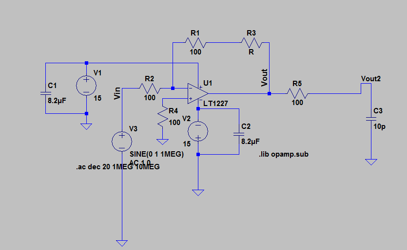
Schematic for the amplifier:
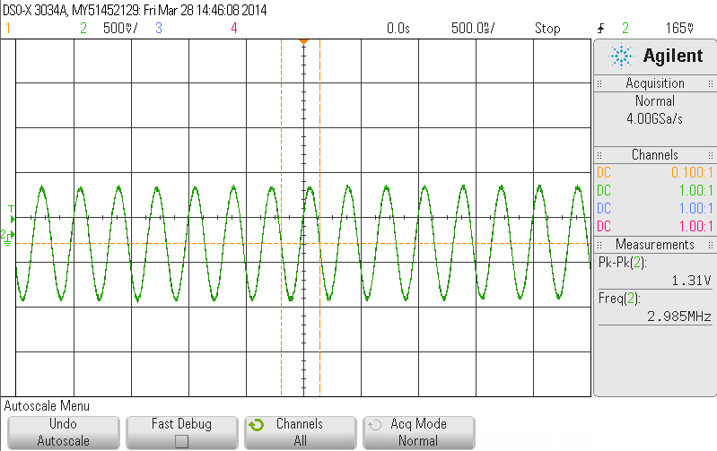
 Before connect it to amplifier circuit:
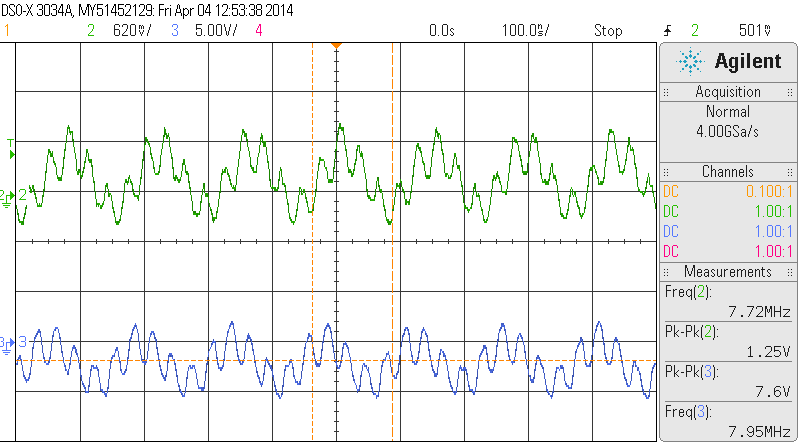
 Why the sine wave will distorted? any possible reason? is this due to noise?
blue is the input signal of an amplifier and green is the output signal
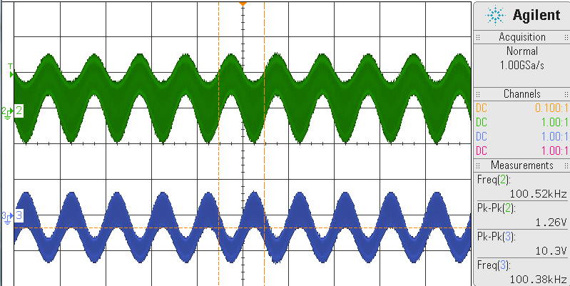
![1MHz]](https://i.sstatic.net/SGYWh.png)
Schematic for the amplifier:
 Before connect it to amplifier circuit:
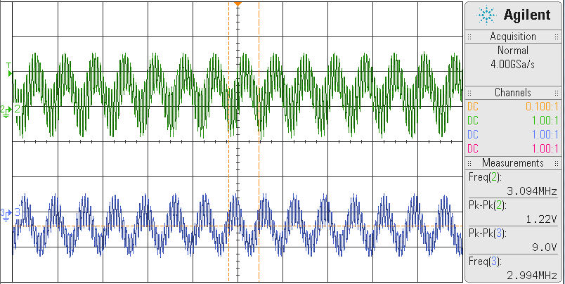
 Why the sine wave will distorted? any possible reason? is this due to noise?
blue is the input signal of an amplifier and green is the output signal

![1MHz]](https://i.sstatic.net/SGYWh.png)


Check this out from the datasheet:
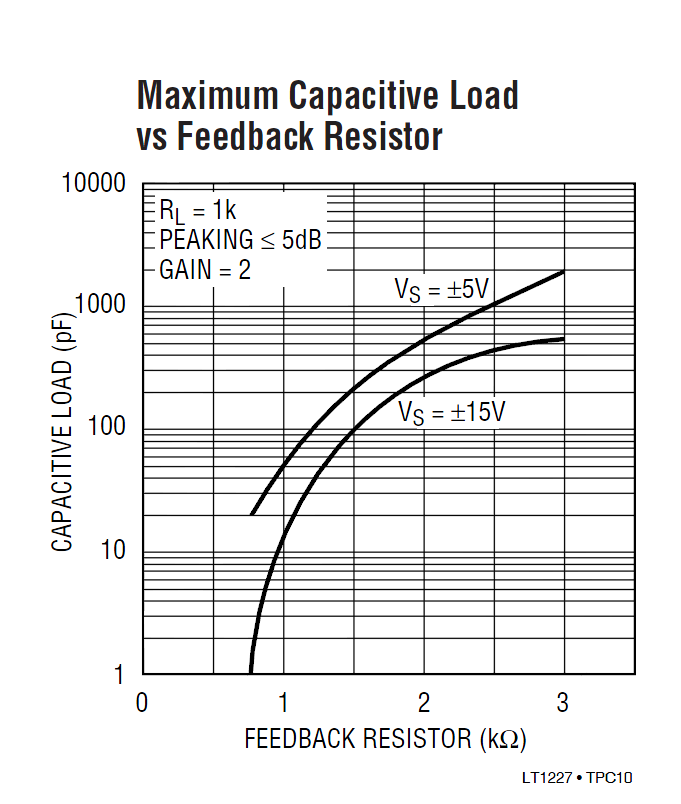
If your feedback resistor is much less than about 1K with +/-15V supplies, it's going to oscillate like a banshee with only a tiny amount of load capacitance (such as a scope probe).
The circuit is oscillating.
The reason is as follows: The opamp is a current-feedback amplifier which needs a feedback resistor that must exceed a certain limit (specified by the manufacturer).
You should consult the data sheet to see the lower limit of this feedback resistor - typically, some hundreds of ohms.
(By the way: Don´t worry about capacitors in parallel to the power supply; they are useless in simulation as long as the dc source is ideal).
On a quick look, I see one problem is that you have relatively large power supply decoupling capacitors. These are likely to have a large-ish internal resistance/inductance. This might permit the op-amp to oscillate. Try adding 0.1uF caps from V+ and V- to ground, near to the op amp.
Almost certainly, the center of the problem is that the op amp is oscillating at some high frequency, and that oscillation is added to your intended signal. This could be caused by power supply connections whose voltage varies when the op amp tries to draw rapidly changing current. That's why my suggestion to add fast-responding bypass capacitors.
Or it could be caused by some capacitance of the load (possibly the scope probe) causing the feedback loop to have some delay (phase shift), resulting in the feedback being positive for some frequencies.