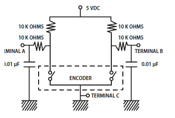
I've got a funny problem with interrupts and PWM signals that's causing false interrupts to trigger. What exactly is happening is that I'm using a hardware debounced quadrature rotary encoder. The pulses from the encoder are connected to interrupts which then I can determine the direction of rotation. Pretty standard routine. This works fine on it's own.

Now, I introduce a PWM output into my project. In this case, lets say I am dimming an LED. I load my program and the led works fine. When I rotate the encoder one "click", It appears that there are multiple interrupts that are triggered on the encoder..on the order of about 16 times the amount expected.
I've simplified the code all the way down and I've tried different different combinations of PWM and Interrupt pins and the response is always the same. The one bizarre thing I notice is that if I disconnect the jumper wire from the PWM pin to the LED, the problem goes away and the encoder starts behaving like it should. I'm baffled and can't figure out what's going on here?
How can I debug or test this? What's with the PWM jumper unplug and interrupts working properly? What does this sound like?
Also, I've asked this question on the Netduino and GHI electronics forums and haven't received any solutions.

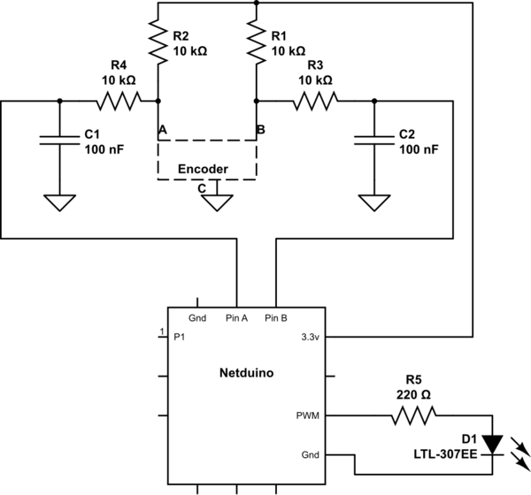
simulate this circuit – Schematic created using CircuitLab
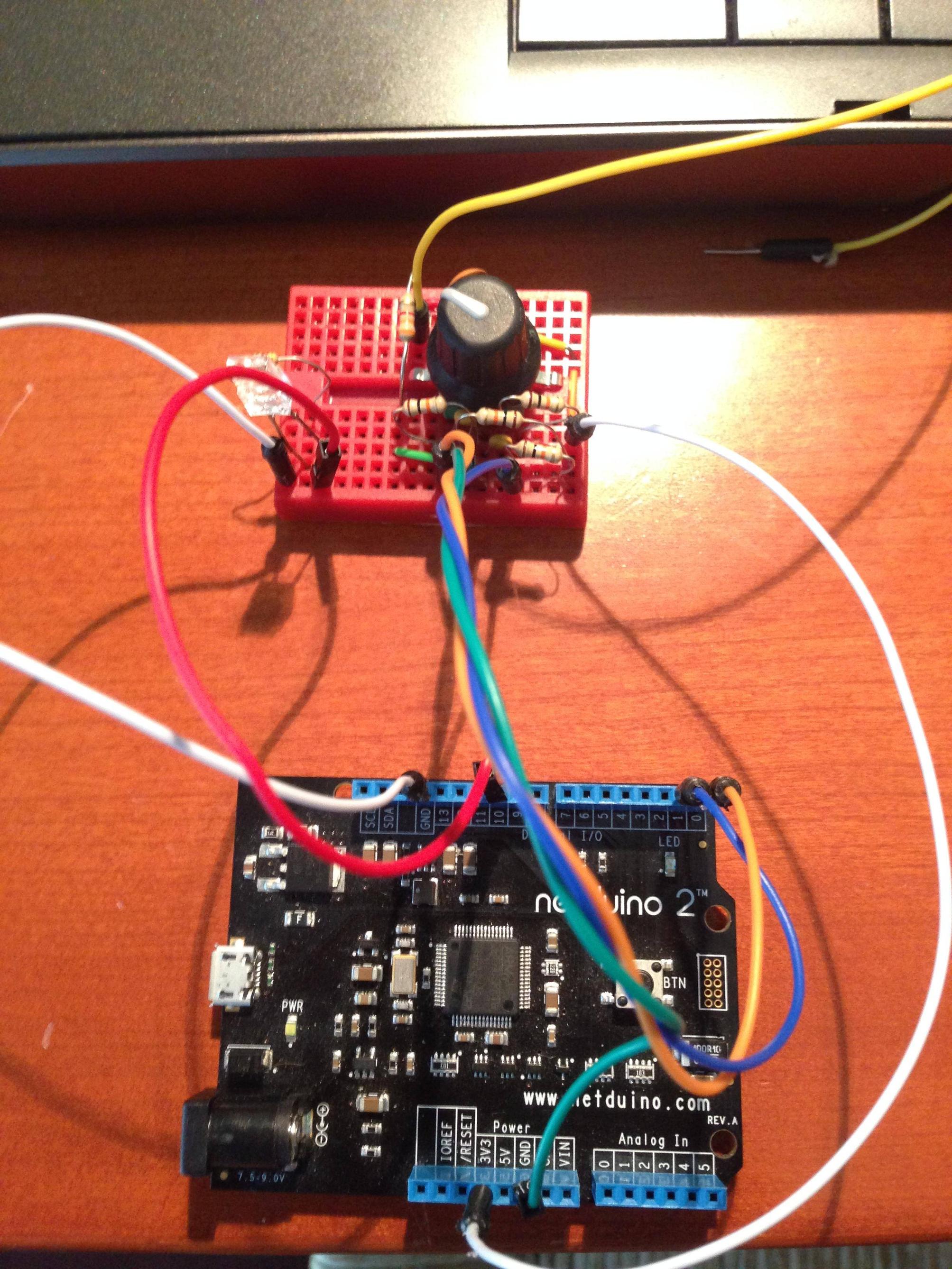
Actual Circuit:

Update: Based on the help in the comments, I've uncovered that there is some type of noise induced in the PWM jumper wires which affect the jumper wires connected to the rotary encoder. When the PWM jumper wires are near the encoder jumper wires, the problem condition exists. How to I eliminate this noise, other than keeping the jumper wires apart from each other. Furthermore, how do you eliminate this noise in the case of PCB traces?
