5
\$\begingroup\$

I have a BeMicro CV low cost dev board from Altera. It features a Cyclone V.

FYI: Schematics and gerber here

They routed impedance controlled differential lines to some dual 2.54mm standard headers.

See the at the top of the picture below: enter image description here
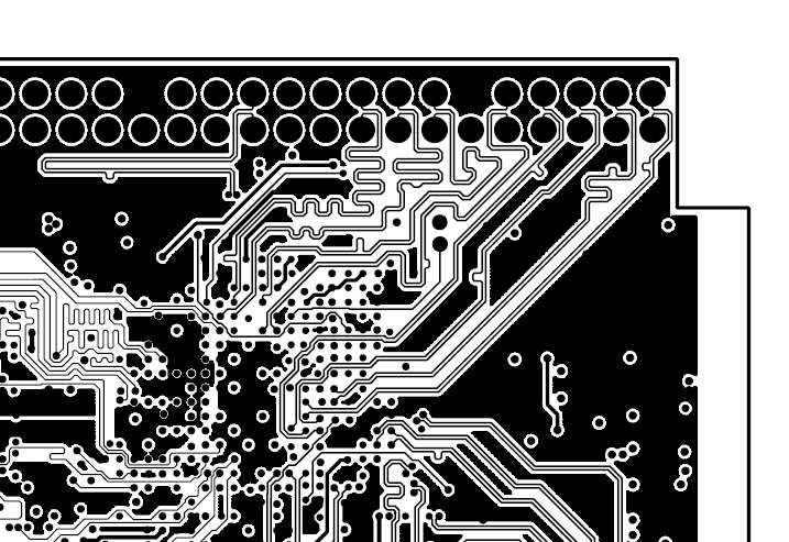
It seems that they cared about the controlled impedance, and also the line lengths.

I would like to connect a 1000Mbit PHY with GMII interface (parallel 125MHz clock).

Can I plug a daughter board to this one and convey the 125MHz signals using a simple 2.45mm header?

\$\endgroup\$
7
  • 3
    \$\begingroup\$ The question you should ask yourself is, why would the designer expend the effort to route the signals, particularly all the fiddling with matched lengths and impedance control, if they didn't expect it to work? The short answer is, it should work perfectly well - especially if you take the same kind of care with your daughter board. \$\endgroup\$
    – markt
    Commented Apr 17, 2014 at 7:05
  • 1
    \$\begingroup\$ Given that they're differential traces, and given the likely LVDS signalling capabilities of the FPGA, I'd expect them to work perfectly well up to several hundred MHz if not a GHz or so. Also, you could always ask the vendor of the board. \$\endgroup\$
    – markt
    Commented Apr 17, 2014 at 7:17
  • 1
    \$\begingroup\$ Try to get the RLC model of the connector from tyco or samtec. You can simulate the whole path. suggestion is altera very good company without proper thought they will not include these headers in to the board and Differential traces will be more tolerant to SI compared to Single ended signals. \$\endgroup\$
    – user19579
    Commented Apr 17, 2014 at 7:44
  • 2
    \$\begingroup\$ Try to get the RLC model of the connector from tyco or samtec. You can simulate the whole path. suggestion is altera very good company without proper thought they will not include these headers in to the board and Differential traces will be more tolerant to SI compared to Single ended signals.I have just downloaded Single line Model of AMPMODU type connector and see R=12m,L=2.5n,C=0.6p--> These values are very less. They will not cause much loading. Tpd is around 39ps which is also very less. \$\endgroup\$
    – user19579
    Commented Apr 17, 2014 at 7:59
  • 1
    \$\begingroup\$ @user19579 Other answer are good too but your comment is the most useful to me, I think. You should convert it to an answer and I will accept it. \$\endgroup\$
    – Blup1980
    Commented Apr 18, 2014 at 10:25

2 Answers 2

4
\$\begingroup\$

I think it should work. These connectors seem to have relatively low capacitance.

If you are really worry about this - you may try to pass 125MHz or even faster signal from lab generator and see what is going on oscilloscope.

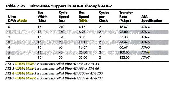
These connectors were used for ATA hard disks, and they were working with pretty long ribbon wire with bus speed up to 33MHz, so without that ribbon cable there should be no problem with 125MHz (or 125MHz differential signal).

ata bus frequency

Source:

Upgrading and Repairing PCs Scott Mueller

http://books.google.com/books?id=E1p2FDL7P5QC

\$\endgroup\$
1
\$\begingroup\$

Although the lines look like matched pairs, they are not (by the look of it) matched between themsleves, so the delays on each of your databits is likely to be different. This will eat into the margin that your interface has (unless you are making a custom daughterboard, in which case you can compensate for the differences in delay on by making your traces shorter where they connect to long traces on the main board.

Having said that, the differences are likely to be very small, and at 125MHz single-data rate (which is what GMII is), I imagine you'd be OK.

More of an issue might be if there are enough ground connections to enable the signals to make it across cleanly. If there are very few ground connections, you will get "ground-bounce", which in the worst case makes your clock look like it has two edges where there should be one!

\$\endgroup\$

Your Answer

By clicking “Post Your Answer”, you agree to our terms of service and acknowledge you have read our privacy policy.

Not the answer you're looking for? Browse other questions tagged or ask your own question.