I've seen that a number of schematics will connect the center (common) pin of a potentiometer to one or the other leg, and it then functions more like a rheostat. Is that how a rheostat is wired internally? What's the difference between a potentiometer and a rheostat? Finally, why connect the common to a leg at all on a potentiometer, instead of just ignoring the unused leg?
5 Answers
The correct term for the common terminal of a potentiometer is the slider.
A rheostat is simply a variable resistance used to control power to a load and you are correct about the wiring. Only the slider and one other terminal are used.
A potentiometer uses all three terminals, enabling a variable voltage or signal to be tapped off from the slider.
Potentiometers and rheostats are made the same way, but rheostats are usually much "beefier", as they are generally used in high-power situations.
The slider is often connected to one or other terminal for safety reasons, in case it loses contact with the track.
-
\$\begingroup\$ In the event the slider loses contact with the track, wouldn't the resistance from the terminal in use to the slider terminal be the same as an open connection (air)? Assuming a 10K pot, is this safer than having a sudden 10K resistance? Just curious about this point. Thanks for the excellent answer. \$\endgroup\$– JYeltonCommented Mar 4, 2011 at 21:40
-
2\$\begingroup\$ Sometimes rheostats are used to set the gain of a system; a circuit may be designed so the highest resistance setting will produce e.g. a gain of ten, but an open circuit might produce a gain of 1,000. In such cases, having the contact momentarily open to expose the full resistance of the element would produce an excessive level of gain, but not the super-excessive level that would be caused if the element weren't connected as a "backup". \$\endgroup\$– supercatCommented Mar 4, 2011 at 23:47
-
18\$\begingroup\$ Sometimes the slider is called a wiper. \$\endgroup\$– Thomas OCommented May 18, 2011 at 18:43
-
1\$\begingroup\$ carbon pile rheostats don't have a slider just one terminal at each end and a force-sensitive resistor between. \$\endgroup\$ Commented Nov 15, 2015 at 7:00
-
\$\begingroup\$ Assuming you are using two terminals on a pot like a rheostst, why would a wiring schematic specify that the other (third), output terminal on a pot be connected to ground? \$\endgroup\$ Commented Jan 9, 2023 at 3:01
It appears the Wikipedia article about potentiometers quite clearly and concisely points out the difference:
A potentiometer /pɵˌtɛnʃiˈɒmɨtər/, informally a pot, is a three-terminal resistor with a sliding or rotating contact that forms an adjustable voltage divider.[1] If only two terminals are used, one end and the wiper, it acts as a variable resistor or rheostat.
It also has a dedicated section for the (historical) meaning of "Rheostat", and how rheostats were/are built, but admits that the word "rheostat" is becoming obsolete in favor of the more general "potentiometer", which, as already highlighted in the introduction paragraph, is just a rheostat if you ignore one of its terminals.
The term "rheostat" is becoming obsolete,[9] with the general term "potentiometer" replacing it. For low-power applications (less than about 1 watt) a three-terminal potentiometer is often used, with one terminal unconnected or connected to the wiper.
-
6\$\begingroup\$ I would still consider the term "rheostat" as useful to distinguish cases where a device is used to set an absolute resistance rather than establish a resistor ratio with an indeterminate resistance in series with the sense pin. \$\endgroup\$– supercatCommented May 3, 2016 at 14:20
One difference not yet mentioned between devices intended for rheostats versus those intended for use as pots: if a device will be used as a rheostat, it is important that the wiper resistance be fairly small, and even more important that it be 'well-behaved'. If the device will be used as a pot, and the amount of current flowing through the wiper will be minimal, wiper resistance is relatively unimportant. A 100-ohm rheostat with a wiper resistance of 10 ohms in some spots and 1,000 ohms in other spots would be totally useless. A 100-ohm pot with such behavior could be just fine, however, if it was being used to drive a high-impedance input. Note that such a pot would be roughly equivalent to a 1,000-ohm pot in parallel that had a 110-ohm fixed resistor tied between the ends.
A Rheostat is used to vary the amount of current in the circuit but a potentiometer used to vary the voltage between the second terminal and one of the outside terminal
Another difference not mentioned here is accuracy. If you use a potentiometer you are using it as a ratio between two values. Like a voltage divider. Its absolute value tolerance may not be very good, but if you only care about the ratio set by the wiper, the pot is much more consistent over many devices and temperature.
But if a rheostat configuration is used, say in series to vary the current through a load, its absolute value is used. Not as consistent.
This applies to digital pots as well. See any datasheet to see error curves between the two.
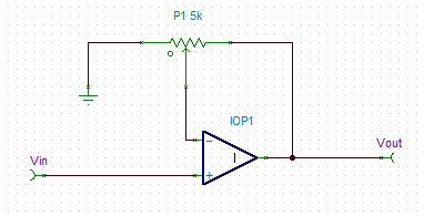
For example this is the more accurate way to use a pot for variable opamp gain.
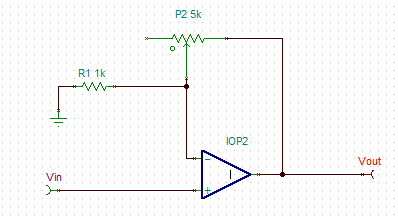
Below is not the way to get the best accuracy from a variable gain amp. It's using the absolute value of the pot not the ratio set by the wiper.


