0
\$\begingroup\$

I'd like to drive three common anode 7.5v 10ma 7-segment displays using my arduino uno and a few 74HC595N shift registers. The problem is the uno only outputs 5v 40ma on the digital pins.

I am considering inverting the 5v-out to -5v using an ICL7660. The -5v could then be placed at the anodes for a 10v total drop.

I have a few questions before trying this out-

Would the ICL7660 sink enough current to drive all three 7-segments? Are there other drawbacks? Is there a better solution?

Resources:
The 7-Segment Display
ICL7660 Arduino tutorial

\$\endgroup\$

3 Answers 3

1
\$\begingroup\$

No, the 7660 is of no use. It can only supply enough current for a couple of segments, let alone displays.

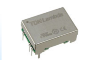
The easiest (not necessarily the cheapest) way to get enough voltage for this display is to use a DC-DC converter, such as a TDK CC3-0512SF-E:

enter image description here

This one will output 12V at up to 250mA, so for a 3-digit display 10mA/segment is okay.

You will also need one resistor per segment of about 470 ohms, three ULN2003A darlington arrays.

If you have 9-12V available somewhere else, you won't need the DC-DC converter, but you will still need the resistors and the ULN2003As.

\$\endgroup\$
2
  • \$\begingroup\$ Thanks, I realize I got cathode/anode mixed up. How about a 12v external supply on the anodes and 5/0v on the arduino to control the LEDs? This way I wouldn't need the ULN2003A. Would that work? \$\endgroup\$
    – ksariash
    Commented May 17, 2014 at 22:38
  • \$\begingroup\$ It might work (in fact I've made a product that used that method with temperature compensated anode voltage), but I was rather reluctant to suggest it because it multiplies the ways you could fry your Arduino, and the ULN2003s are both cheap and well rated to switch the high voltage at appropriate total current. \$\endgroup\$ Commented May 17, 2014 at 23:07
0
\$\begingroup\$

I'm getting the impression you don't know how to control the current thru a LED (segmented or otherwise). Placing -5V at the anode sounds bizarre to me. You need a positive supply of about 10V attached to the anode and it's more effective to use a boost switching regulator that uses an inductor. Forget about trying to generate a negative rail.

For the cathodes, use small N ch mosfets driven from the individual outputs of the shift register. Use a current limiting resistor in series with each cathode - it will need to "drop" 2.5V at 10mA and as such, a 270 ohm resistor would be OK.

\$\endgroup\$
2
  • \$\begingroup\$ I was looking at this question and thought maybe something like an SN7407 pdf datasheet would be suitable? \$\endgroup\$ Commented May 17, 2014 at 21:05
  • \$\begingroup\$ @AndrewMorton it might do the trick or a ULN2003 \$\endgroup\$
    – Andy aka
    Commented May 17, 2014 at 21:07
0
\$\begingroup\$

You can use 2N3906 PNP transistor with 4.7k resistor for each common anode pin.

\$\endgroup\$

Your Answer

By clicking “Post Your Answer”, you agree to our terms of service and acknowledge you have read our privacy policy.

Not the answer you're looking for? Browse other questions tagged or ask your own question.