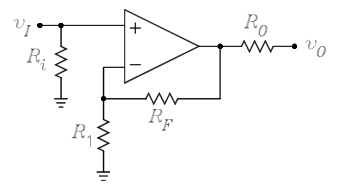
In many of the explanations I've read of non-inverting op-amps, the non-inverting input is given a resistance to meet the specs of the op-amp. I'm confused by how the resistance is applied. Since the resistor is just acting to control the input current, I expected it to be inline with the input voltage. However, the resistor is usually attached as a tee from the input going to ground. Why is the input resistor on a tee and not just inline with the non-inverting input?

6 Answers
Let the resistance looking into the non-inverting input be \$R_{in+}\$
If a resistor \$R_i\$ is placed in series with the non-inverting input, the resistance seen by the source \$v_I\$ is
$$R_I = R_i + R_{in+} \ge R_{in+}$$
If a resistor \$R_i\$ is placed in parallel with the non-inverting input, the resistance seen by the source \$v_I\$ is
$$R_I = R_i||R_{in+} \le R_{in+}$$
Since, for an ideal op-amp, \$R_{in+} = \infty\$, the series case gives
$$R_I = R_i + \infty = \infty$$
while for the parallel case
$$R_I = R_i||\infty = R_i$$
There are two functions of a shunt resistor on an inverting input. One is in the case when you need a termination resistor, like in the case when the signal is brought in on a coax or strip line. The second reason is more subtle, in the non-ideal case (i.e. every real Op-amp) the input has leakage currents, which interact with the various resistances to create a offset voltage on the input to the op-amp. To partially compensate for this, the resistances seen by each input must be matched, that means in your example, that \$R_{in} = R_1||R_f\$, where the symbol \$||\$ means "in parallel with".
The resistor does not control the input current. Ideally, there is no input current because the + input has infinite resistance.
What R1 does is it establishes a finite input impedance for the amplifier.
The op-amp's natural very high impedance is not necessary or desirable in some applications.
Also, op-amp inputs generate small DC bias currents: some models more than others. This current needs a path to allow it to flow to the ground, called a "DC return" path. The resistor provides that path.
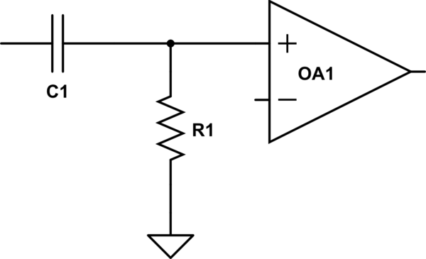
Suppose that the broader circuit is like this:

simulate this circuit – Schematic created using CircuitLab
The source device happens to be capacitively coupled, represented by C1. (C1 could be part of the amplifier based around OA1, or it could be part of the source device; it doesn't matter.)
So, the only DC path from the + input to ground is through the resistor!
What happens if you remove the resistor? Or connect it incorrectly, in series between the capacitor and non-inverting input? Current flowing out of the + input will slowly charge C1 until a voltage builds up that pushes the + input out of the common mode input range. R1 helps keep C1 discharged.
Note, however, that the bias current flowing across R1 generates a voltage on R1 (V = IR) which creates an offset voltage which gets amplified.
If the op-amp has similar bias currents flowing out of both inputs, this problem can be attacked by choosing a value of R1 which is the same as the combined resistance faced by the - input, as a result of the feedback resistor network.
Thus R1 is chosen in order to establish some desired input impedance, and the magnitudes of the feedback resistors are chosen to balance the bias current to null the offset (while their ratio is chosen for the desired gain).
Some op-amps have built in bias current cancellation. These op-amps have a much smaller bias currents than similar op-amps without the cancellation. Moreover, the remaining uncancelled currents from the two inputs are not similar at all, and may be of different polarity. With these op-amps, the trick of balancing the resistances is not applicable; R1 can be chosen independently of R2 and R3. For instance R1 could be, say, 100 kOhm to set up an input impedance that high, whereas the feedback resistors could be chosen only in the thousands of ohms.
Briefly, to summarize, there are two motivations:
To minimize the drift of the output due to the bias input current (offset).
In this case \$R_{in}=R_{1}//R{f}\$To match the input impedance (i.e. in video amplifier).
In this case \$R_{in}\$ must be equal to the impedance of the source, for example 75Ω for coaxial cable in analog video.
Sometime, in case of ac-coupled amplifier, \$R_{in}\$ provide the return-to-ground path for the input current, as said in the "Horowitz-Hill".
If your signal into the circuit is referenced to a dc value between the rails of the power supplies (normally 0V or mid-rail) then you don't need an input resistor. You typically use an input resistor to make a "light" connection to midrail (0V) when coupling an input via a capacitor.
If you remember, an ideal op-amp's inputs do not allow flow of current. So, without a route to ground, the loop's gain will be infinity because no current is flowing there.
-
2\$\begingroup\$ I'm sorry, I disagree. The op-amp loop gain will be 1 + \$\dfrac{R_F}{R_1}\$ irrespective of their being a resistor (R\$_i\$) there or not. \$\endgroup\$– Andy akaCommented May 18, 2014 at 17:21
-
1\$\begingroup\$ exactly, this answer is wrong. \$\endgroup\$ Commented May 18, 2014 at 17:36
-
\$\begingroup\$ To me, the loop gain is the gain of the complete loop, that is: Aol*R1/(R1+Rf). \$\endgroup\$– LvWCommented May 18, 2014 at 18:51
