I am building an AC dimmer circuit to control from an Arduino using this schematic:

I need to make this dimmer so that it can be used as a three way switch as well. How would I modify this circuit to work in place of a three way switch?
I am building an AC dimmer circuit to control from an Arduino using this schematic:

I need to make this dimmer so that it can be used as a three way switch as well. How would I modify this circuit to work in place of a three way switch?
I would have both switches connected to the Arduino, with the Arduino firmware allowing both switches to control the same dimmer.
For this to work, you would have "bright" and "dim" switches at both control points, rather than having a pot somewhere to control the dimmer. (For bonus points, you could have rotary encoders at both locations, rather than switches. :-) )
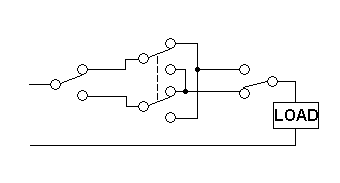
Here's what a three way switch circuit looks like: -

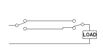
If you only need two locations then omit the more complicated DPDT in the centre: -

Should it be that you want the switches going to the MCU then please note that they enact the logical ex-or function.