0
\$\begingroup\$

I'm trying to read capacitor output values as the cap discharges for a physics project, and am getting a high voltage while charging, but dropping to 0V 3000 \$\mu\$s after stopping the charging signal, which doesn't seem right.

Schematic: Arduino Schematic
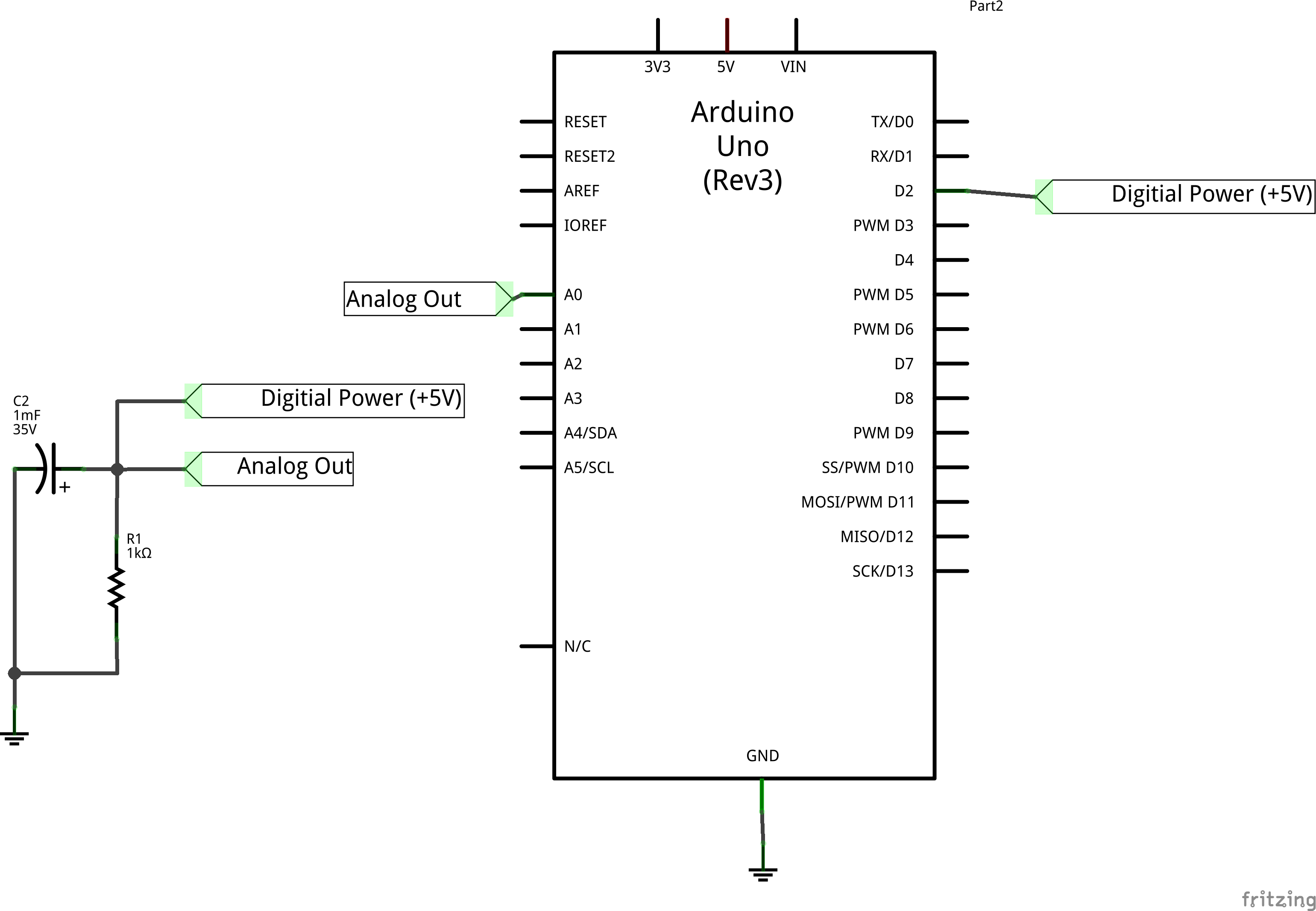
The cap is 1mF, resistor 1k\$\Omega\$.

I'm trying to charge the cap by sending +5V out through the digital line for 2 seconds, and then trying to discharge by either switching the digital output line to high-impedance (by switching it into input mode, pinMode(DIGITAL_OUTPUT, INPUT);) or by writing a low signal (digitalWrite(DIGITAL_OUTPUT, LOW);).

I've tried both methods of triggering discharge, but the analog signal that I've read (analogRead(ANALOG_INPUT);) has gone from +5V while charging down to 0V 3000\$\mu\$s after. I was under the impression that the cap should take at least 2 seconds to fully discharge.

I assume I've messed up the circuitry somehow, and the code is actually working after enough debugging, so I haven't wasted space with 97 lines of code, but the code is in a pastebin if the circuit looks like it should work.

\$\endgroup\$
4
  • 1
    \$\begingroup\$ Outputting a low doesn't result in a high-impedance connection. \$\endgroup\$ Commented May 19, 2014 at 23:41
  • \$\begingroup\$ @IgnacioVazquez-Abrams Yes, I was saying that I tried both outputting a low and setting the pin to high-impedance in two different debugging trials. \$\endgroup\$ Commented May 19, 2014 at 23:57
  • \$\begingroup\$ @IgnacioVazquez-Abrams Changing the pin to INPUT should make it high-Z, drawing minimal current \$\endgroup\$
    – EkriirkE
    Commented May 20, 2014 at 7:22
  • \$\begingroup\$ @EkriirkE: That's correct. But some current will still leak though the S+H circuit of the analog input. \$\endgroup\$ Commented May 20, 2014 at 7:43

3 Answers 3

3
\$\begingroup\$

Are you sure the capacitor is 1mF (1 milliFarad) as opposed to the more common value of 1uF (1 microFarad). A 1 uF capacitor with a 1 K resistor would give you a time constant of 1000 us, so after 3000 us, you should expect to see a voltage of < 5%.

\$\endgroup\$
4
  • \$\begingroup\$ Note that 1 mF capacitors are commonly labeled as 1000 uF. \$\endgroup\$
    – Zuofu
    Commented May 19, 2014 at 23:40
  • \$\begingroup\$ Looks like I mislabeled the components I got a few years ago. Popped in a 10uF resistor and it took a while to discharge. Now I need to figure out what these caps are... Hey, I just gave myself a good physics project! Thanks for the suggestion. \$\endgroup\$ Commented May 19, 2014 at 23:53
  • 2
    \$\begingroup\$ @RyanLeonard . Next time I need to discharge a 10uF RESISTOR, I am going to look you up. (Gentle reminder to review what you type. Others depend upon our accurate comments and answers.) \$\endgroup\$
    – Marla
    Commented May 20, 2014 at 1:42
  • \$\begingroup\$ @Marla Heh, I appreciate the reminder. I'd edit if I had a little more rep. \$\endgroup\$ Commented May 20, 2014 at 12:52
2
\$\begingroup\$

A couple of things:

Is this a 1mF capacitor? That is, 1000uF? That's an awfully big one!

Put a resistor in series with your charging pin... like 10k. It will take some time to charge up, but it will lessen the effect if it's the digital pin causing the discharge to happen. You technically should have a resistor in there anyway, because there is nothing to limit the current rushing into the capacitor from the poor, abused microcontroller's digital pin.

Assuming your pin can handle about 20mA, the smallest resistor in any case should be 5v / 20mA = 250 Ohms. This will keep the capacitor from drawing too much current from the micro during the instant when the cap charging begins.

One thing you could try is to just touch the +5v line to the cap to charge it, then physically take it off, measuring the result. See if it's different than having the pin switch.

\$\endgroup\$
0
\$\begingroup\$

I was using a cap less than 10\$\mu\$F. Solved by replacing the "1 mF" cap with a 10\$\mu\$F cap. Oops!

\$\endgroup\$
2
  • \$\begingroup\$ Please use the edit link on your question to add additional information. The Post Answer button should be used only for complete answers to the question. \$\endgroup\$ Commented May 20, 2014 at 0:52
  • \$\begingroup\$ @placeholder Sorry, I thought that the other responses were more complicated to follow for future users. My problem was a mislabeled capacitor. It was simply solved by trying a different cap. I appreciated the extra information given, but none of them offered a solution, only different suggestions. Thanks for taking the time to suggest the proper use of the sites. \$\endgroup\$ Commented May 20, 2014 at 12:48

Your Answer

By clicking “Post Your Answer”, you agree to our terms of service and acknowledge you have read our privacy policy.

Not the answer you're looking for? Browse other questions tagged or ask your own question.