2
\$\begingroup\$

I've got two solar panels which each provide 9V. I need them to provide 18V, and according to different sources (such as this forum thread) that should simply be a matter of connecting them in series.

So I did. I connected the negative on panel A with positive on panel B, and positive on panel A with negative on panel B. As far as I understand, this is how you connect solar panels in series.

However, I came across a surprising observation. Each of the panels produce about 10V - 11V each on a good sunny day. I've checked (and double checked) readings on my multimeter. However, when I connect them in series the voltage drops to 4V - 5V. I get this reading on both solar panels by connecting my multimeter to the connectors on any two of the solar panels. As you've probably figured out, I don't understand why this happens.

Now, the panels have 4 soldering connectors each (see below picture). The first two are positive and negative (which according to my multimeter outputs nothing) and the two second ones have some chinese letters next to them which I've got no idea what means. However, these connectors (the ones with chinese symbols next to them) are the ones giving 10V - 11V. These are also the ones I've used to create a connection from panel A to panel B.

Since I could not figure this thing out, I called a friend. I was advised to put Schottky diodes in between them in case the panels somehow was discharging through each other. So I did. However, still only 4V - 5V when i put them in series.
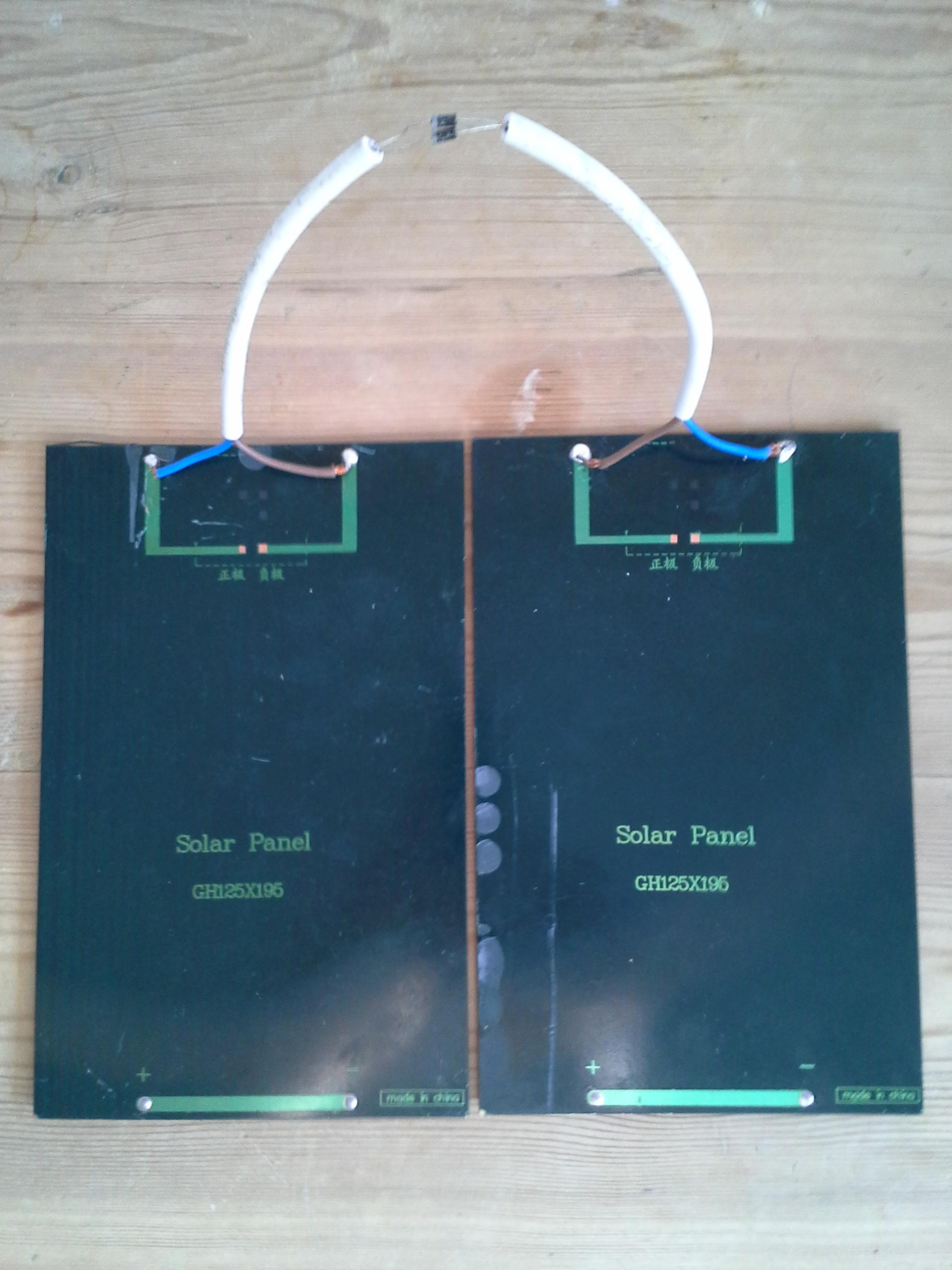
enter image description here

Right now, I'm at loss what to do. How do I connect these panels in series to get 18V from them?

To summarize:

  • Each panel outputs 10V - 11V
  • Connecting my multimeter to the bottom and top right hand (or left hand) connectors indicates resistance, so these can't be the same connectors as that should give zero resistance as far as I've been told.
  • The connected solar panels give 4V - 5V regardless of whether I've got the Schottky diodes in the middle or not.

What am I doing wrong?

\$\endgroup\$
1
  • 1
    \$\begingroup\$ Don't go by wire colour, as it appears they are both wired differently. \$\endgroup\$
    – EkriirkE
    Commented May 22, 2014 at 18:42

4 Answers 4

6
\$\begingroup\$

If I've understood correctly, you connected positive to negative and positive to negative. In other words, you've connected both wires on one panel to both wires on the other. This is almost what you want. You want to make one connection between the two panels, positive-to-negative but leave the other two wires free. You connect your load to the two open wires.

You've basically shorted out the two panels. The only reason nothing burned up is that the panels cannot generate much current.

\$\endgroup\$
2
  • \$\begingroup\$ Alright, so (as i also aksed EkriirkE) I should then connect the remaining free wires to my battery then, would that be right? \$\endgroup\$
    – sbrattla
    Commented May 22, 2014 at 18:58
  • \$\begingroup\$ I'm marking this as the correct answer, as it after all was the first one and apparently a correct one. \$\endgroup\$
    – sbrattla
    Commented May 22, 2014 at 19:05
6
\$\begingroup\$

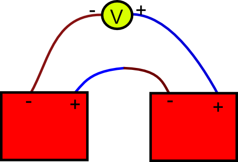
I connected the negative on panel A with positive on panel B

This is a good start

and positive on panel A with negative on panel B

But what is with this?

enter image description here

This is how it should be done.

And what is with the diodes? You should only use a diode when having a dual supply (panel and other supply) and you want to prevent current from the supply going into the solar panel.

\$\endgroup\$
4
  • \$\begingroup\$ The V symbol, does that represent a battery? \$\endgroup\$
    – sbrattla
    Commented May 22, 2014 at 18:59
  • 1
    \$\begingroup\$ @sbrattla it represents a voltmeter in the schematic. There you also connect your load (device). \$\endgroup\$
    – Cornelius
    Commented May 22, 2014 at 19:00
  • \$\begingroup\$ Ah, but the two other answers say I should only connect + and - between the panels, and leave the remaining two open. Doesn't that go opposite of what you suggest? \$\endgroup\$
    – sbrattla
    Commented May 22, 2014 at 19:02
  • \$\begingroup\$ The other two answers suggest the same thing. I drawn that schematic to help you measure the correct voltage of 18V. \$\endgroup\$
    – Cornelius
    Commented May 22, 2014 at 19:03
3
\$\begingroup\$

You are shorting your panels. And panels do not "discharge" panels. They could possibly discharge a battery if there is no light, and yes the Schottky would help that instance.
The diodes are only really a good idea if you expect power to return to the panels, e.g. from charging a battery.
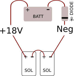
This is what you want:
Neg 18V - panel +- panel + Pos 18V

If you are using these directly connected to a battery then the Diode is a good idea: Neg 18V - panel +- panel +__[>|]__ Pos 18V

enter image description here

I also see your panels have the wiring mixed in colouring, so do not assume polarity based on the wire colour...

\$\endgroup\$
4
  • \$\begingroup\$ Ah, so to flesh it out (I'm a total beginners) I would connect positive on A to negative on B, and then negative on A to negative on battery and positive on B to positive on battery? \$\endgroup\$
    – sbrattla
    Commented May 22, 2014 at 18:57
  • 2
    \$\begingroup\$ Correct. And since you are doing a battery charger circuit, do indeed use the schottkey on one side of the circuit. \$\endgroup\$
    – EkriirkE
    Commented May 22, 2014 at 19:01
  • \$\begingroup\$ Alright, so I only need a single diode, not a diode on both? I though I needed a diode on both + and -, but that explains why only a single Schottky diode came with the panels :-) \$\endgroup\$
    – sbrattla
    Commented May 22, 2014 at 19:03
  • \$\begingroup\$ You only need one, but you can put the diodes in parallel on the same section of the circuit (as it appears you have done) to reduce voltage drop. But Schottkys already have a low drop as-is \$\endgroup\$
    – EkriirkE
    Commented May 22, 2014 at 19:09
0
\$\begingroup\$

Certainly, 18 V are required to run some toys, torches, etc.

On the plates, connect:

  • the left hand brown (+ve) to the right hand brown (-ve);
  • the outer left hand blue (+ve) to the toy's +ve input and;
  • the right hand blue (-ve) to the toy's -ve input.

Now the toy will get the required voltage and runs at 18 V, Replace the toy with an AVO to test V=18 V.

There is a colour notation error by the manufacturer. Brown should always be used at positive terminal.

\$\endgroup\$

Your Answer

By clicking “Post Your Answer”, you agree to our terms of service and acknowledge you have read our privacy policy.

Not the answer you're looking for? Browse other questions tagged or ask your own question.