1
\$\begingroup\$

I've been lately reading about capacitors, but all the formulae needs of resistance to work. However, there might be cases where resistors aren't present on the charge or discharge paths. Consider the following circuit:
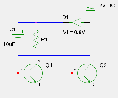
capacitor charge/discharge

Initiallly, both Q1 and Q2 are closed, and the capacitor C1 is discharged.

Then Q2 opens (the capacitor is charged through the diode D1) and then closes.

Q1 opens, the capacitor discharges through it and R1 to ground.

What I want to is calculate the time needed for C1 to charge and discharge, so that I can adjust it to my needs.

I think I'm doing the discharge part right (not sure because of the presence of Q1 there, though).

So my question is, can somebody solve both parts for me on the above circuit so I can get to know how it's done? An explanation would also be useful (i.e.: what resistance value to use when charging in cases like these, as the is no resistor?, does Q1 presence actually matters when calculating discharge times?).

Edit:

Thanks a lot guys. I just drew that circuit on a moment, as I'm myself done a mess with all the capacitor theory and I didn't even express myself properly (with closed I meant: non-conducting, and with open I meant: conducting).

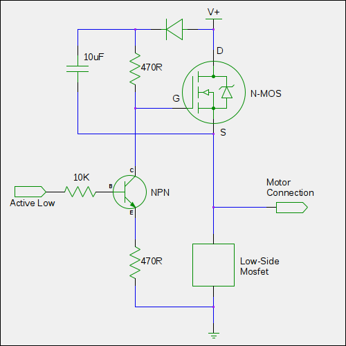
This time I'll put the original image, as I should have done in first place:
enter image description here

This is a basic discrete half-bridge driver for blcd motors (nmos-based), and what I'm trying is to calculate minimum and maximum on-off times that 10uF capacitor could provide, to then, change it according to my needs, if at all needed.

As some of you said and I guessed, the transistor shows some resistance from collector to emitter while coducting, that's ok.

But I'm still not understanding what resistance should I use in the formulae when calculating the charging part if there's no resistor present (npn conducting, low side nmos conducting enough time for the capacitor to charge up, to then let the npn have a rest so the capacitor discharges on to the nmos gate through the resistor, turning it on).

Perhaps it's just a dumb question, I even got a bit stressed looking on the internet for an explanation/tutorial of a capacitor charging/discharging without a resistor, in the hope of getting to understand all this (though I know a resistor is needed in a real circuit to limit the current).

All I can see from the second circuit posted is that the capacitor charges up quicker than it discharges, but can't do the maths because on the charging path there's no resistor, but the diode, so in cases like this, should I use some small value or what?

\$\endgroup\$
2
  • \$\begingroup\$ I hope you meant Q2 is off by saying 'Q2 is closed'. \$\endgroup\$
    – nidhin
    Commented May 25, 2014 at 16:00
  • 2
    \$\begingroup\$ You need to get used to saying "closed circuit", "conducting" or "on" when current is flowing, and "open circuit", "nonconducting" or "off" when it isn't. The way you're using "open" and "closed" is very confusing to everyone else. \$\endgroup\$
    – Dave Tweed
    Commented May 25, 2014 at 19:19

4 Answers 4

3
\$\begingroup\$

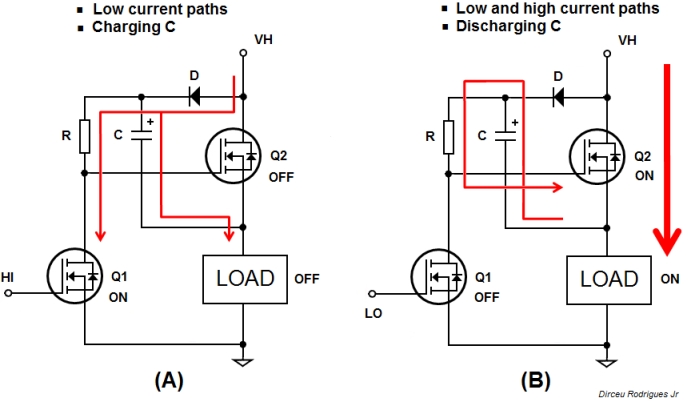
My contribution is to point out a circuit that suits your title: "A path for capacitor's charging, and another for discharging it". It is a solution commonly used to drive a N-channel mosfet/IGBT in the configuration high-side (load grounded). This avoids the use of P-channel mosfet, typically showing higher RDSon. But otherwise imposes a complication when designing N-channel gate drivers (except using a gate voltage larger than the drain voltage - a rare situation). The scheme shown below uses a capacitor as a "floating" gate voltage for the Mosfet. This solution is already integrated in most commercial gate drivers (pick a specific datasheet and note the presence of the diode and capacitor around the component). Motor control and power conversion are typical applications.

Bootstrap

Note: When I started to answer, the author had not yet supplemented the question with the last figure (I took some time drawing my figures). The web page no mantain updated, when editing. I write this so the reader does not think I simply repeated that idea. It happens on forums.

\$\endgroup\$
2
  • \$\begingroup\$ You're more than welcome Dirceu. Thanks so much for the time employed in your drawings. I've been for months now reading up on motor control and such. Buying a driver is no fun, but at the same time, haven't seen anywhere how the capacitor is calculated, but always ready-made circuits, so I've got no reference. Would like to test bootstrap, and then charge pumps. Let's see. \$\endgroup\$ Commented May 25, 2014 at 19:37
  • \$\begingroup\$ The bootstrap is a kind of charge pump.. The value of the bootstrap cap is not that important provided it is much bigger than the gate capacitance and stray capacitances. \$\endgroup\$ Commented May 25, 2014 at 20:26
1
\$\begingroup\$

You can use the Circuitlab simulator to see what is going to happen (it's a web-based SPICE simulation).

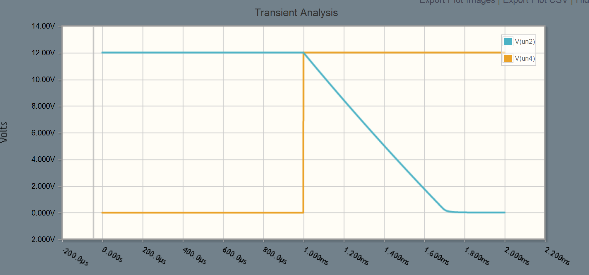
I have not attempted to simulate your circuit, since it doesn't work the way you say you think it does, but I did simulate the discharge of a 10uF capacitor by a common transistor. It's initially charged to 12V, and the transistor discharges it at t=1msec.

schematic

simulate this circuit – Schematic created using CircuitLab

The result was the plot shown below (I did a transient simulation for 2msec using a 1usec step). You can see the input from the 0/12V square wave (orange) and the voltage at the capacitor (cyan). The transistor acts like a constant-current sink until the voltage across the capacitor drops to well under a volt.

enter image description here

The voltage at the collector drops 10.2V in 600usec, so the current must be 170mA. That's a little on the high side for the health of the 2N3904, and it indicates a current gain of about 150, since the base current is about 1.14mA.

So, as you can see, the transistor does not act at all like a resistor. The curve is almost a perfect slope downward (at least in simulation-world, in real life the pulse length is long enough and power dissipation is high enough the slope might curve downward as the die heats, even more different from the exponential discharge you'd get with a resistor).


Edit: With the added diagram it's clear this is a bootstrapped (dynamic) gate driver. Thank you for leaving the original so it does not look like everyone who responded to the initial post was nuts.

The low side MOSFET (with the load resistor) acts as a voltage source when it is on, let's say 0.2V. That's because it has a large load (usually) that will act as a voltage divider with a very small Rds(on). You could say it's close to 0V as an approximation.

The 10uF cap charges from the power supply via the diode. The initial current is probably limited by the power supply rather than the diode drop or the MOSFET so, as Joe Hass said you have to think of some power supply impedance (series resistance etc) to imagine how it starts up. Once the 10uF cap is charged, it just needs to be topped up a bit every PWM cycle.

The capacitor will discharge a bit from the 470R resistor, but normally that would only be during the dead time when both MOSFETs are off. It would also discharge a bit in charging the gate of the high-side MOSFET, but that only happens once per switching cycle (then it gets a top-up during the low time).

This kind of gate driver has to be driven continuously for it to work (or at least driven low, if it's going to sit in one state) and the 10uF capacitor will have an almost constant voltage across it, even when driving a huge MOSFET. A large MOSFET might have 250nC of gate charge, which represents about 25mV of change in the 10uF cap. If you leave it in the high state, the gate voltage will likely leak off and the high-side MOSFET will go linear, leading to smoke and bad stuff. Commercial drivers have an undervoltage lockout circuit (UVLO) that is supposed to prevent this from happening.

The size of the bootstrap capacitor is not very important so long as it is big enough to cover the gate charge of the high-side MOSFET, stray capacitances, and whatever leakage happens in a PWM cycle (usually not much of a factor). 10uF is a reasonable compromise because it's a physically small electrolytic or even a ceramic capacitor and is probably much smaller in capacitance than the power supply filter, so it won't kill your supply and stress the diode too much when the low side MOSFET switches on. Probably 1uF or 100uF would work as well in many cases.

\$\endgroup\$
0
\$\begingroup\$

There are a number of problems with your circuit that you need to solve first. For the capacitor to discharge you need to have a complete circuit for current to flow, because the current that flows out of one capacitor terminal must be exactly matched by a current flowing into the other terminal. Therefore, capacitor can't be discharged unless Q1 and Q2 are both conducting. However, you still won't be able to discharge the capacitor because current will continue to flow through the diode from the 12 V supply, thus keeping the capacitor charged.

To really understand how the circuit might work you will need to include the "real life" characteristics of the power supply, such as an effective series resistance. You also need to understand how a transistor works to know how much current will flow from collector to emitter when it is "open".

\$\endgroup\$
0
\$\begingroup\$

Use the time dependent equation for an rc circuit voltage, solve for t. (Look up rc time constant on Wikipedia) You can get the voltage by subtracting the voltage drop of the diode + voltage drop off the transistor that is on from the supply voltage.

\$\endgroup\$

Your Answer

By clicking “Post Your Answer”, you agree to our terms of service and acknowledge you have read our privacy policy.

Not the answer you're looking for? Browse other questions tagged or ask your own question.