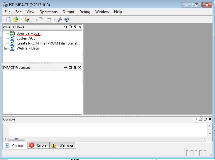
I checked many different posts with the same problem, but none of the advises were helpful thus far. So, I am using ISE 14.7, DLC9G USB Cable, and trying to program the XPLA3 256 CPLD. After successful generation of programming file I click on the 'Configure Target Device' in the processes window and this lunches the IMPACT. The CPLD is directly connected to the programming cable pin-to-pin with no extra peripheral components.

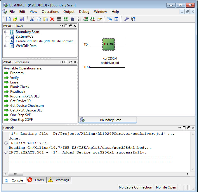
Then I click on Boundary Scan and then right click Add Xlilnx Device and choose the .jed file from the project folder.

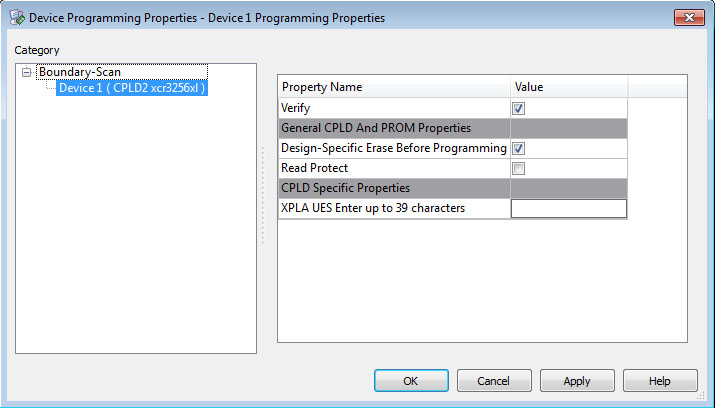
Looks like the device is added successfully. Now, when I right click -> Program on the device, I get a properties window and press OK:

but programming fails. Here's the console output:
----------------------------------------------------------------------
GUI --- Auto connect to cable...
INFO:iMPACT - Digilent Plugin: Plugin Version: 2.4.4
INFO:iMPACT - Digilent Plugin: no JTAG device was found.
AutoDetecting cable. Please wait.
*** WARNING ***: When port is set to auto detect mode, cable speed is set to default 6 MHz regardless of explicit arguments supplied for setting the baud rates
PROGRESS_START - Starting Operation.
Connecting to cable (Usb Port - USB21).
Checking cable driver.
Driver file xusbdfwu.sys found.
Driver version: src=1027, dest=1027.
Driver windrvr6.sys version = 11.3.0.0. WinDriver v11.30 Jungo Connectivity (c) 1997 - 2013 Build Date: May 12 2013 x86_64 64bit SYS 14:54:36, version = 1130.
Cable PID = 0008.
Max current requested during enumeration is 74 mA.
Type = 0x0004.
Cable Type = 3, Revision = 0.
Setting cable speed to 6 MHz.
Cable connection established.
Firmware version = 1303.
File version of C:/Xilinx/14.7/ISE_DS/ISE/data/xusb_xlp.hex = 1303.
Firmware hex file version = 1303.
PLD file version = 0012h.
PLD version = 0012h.
PROGRESS_END - End Operation.
Elapsed time =      1 sec.
Type = 0x0004.
ESN option: 000016D4573401.
INFO:iMPACT - Current time: 5/29/2014 5:22:52 PM
PROGRESS_START - Starting Operation.
INFO:iMPACT:583 - '1': The idcode read from the device does not match the idcode in the bsdl File.
INFO:iMPACT:1578 - '1':  Device IDCODE :        00001111111111111000000000000001
INFO:iMPACT:1579 - '1': Expected IDCODE:    00000100100101001000000000000001
PROGRESS_END - End Operation.
Elapsed time =      0 sec.
Then I tried Debug -> Chain Integrity Test, but it fails too:
INFO:iMPACT - Current time: 5/29/2014 5:26:04 PM
Maximum TCK operating frequency for this device chain: 10000000.
Validating chain...
INFO:iMPACT:1209 - Testing for '0' at position 9.The Instruction capture of the device 1 does not match expected capture.
INFO:iMPACT:1206 - Instruction Capture = '11111111111'
INFO:iMPACT:1207 - Expected    Capture = '10101000001'
INFO:iMPACT:2130 - Boundary-scan chain test failed . Please check tdi->tdo connection between  device:'1' ( 'xcr3256xl') and the cable .
    A problem may exist in the hardware configuration.
    Check that the cable, scan chain, and power connections are intact,
    that the specified scan chain configuration matches the actual hardware, and
    that the power supply is adequate and delivering the correct voltage.
So I checked the connections all over again and everything looks intact. I also checked the BSDL file for this device and in contains the following:
...
attribute INSTRUCTION_CAPTURE of XCR3256XL_TQ144 : entity is "00001" ;
attribute IDCODE_REGISTER of XCR3256XL_TQ144 : entity is "XXXX0100100101001011000010010011";
attribute REGISTER_ACCESS of XCR3256XL_TQ144 : entity is
...
I tried to mask the "Manufacturing section" with 'X's, but it did not help. Please, any more suggestions?
