1
\$\begingroup\$

I needed a reasonably stable 6.2V power supply for my audio amplifier project. I've found a few AIC1563PN dc-dc converters (looks identical to MC34063 according to the datasheet) which I salvaged from some old modems and used one of them as a step-down converter.
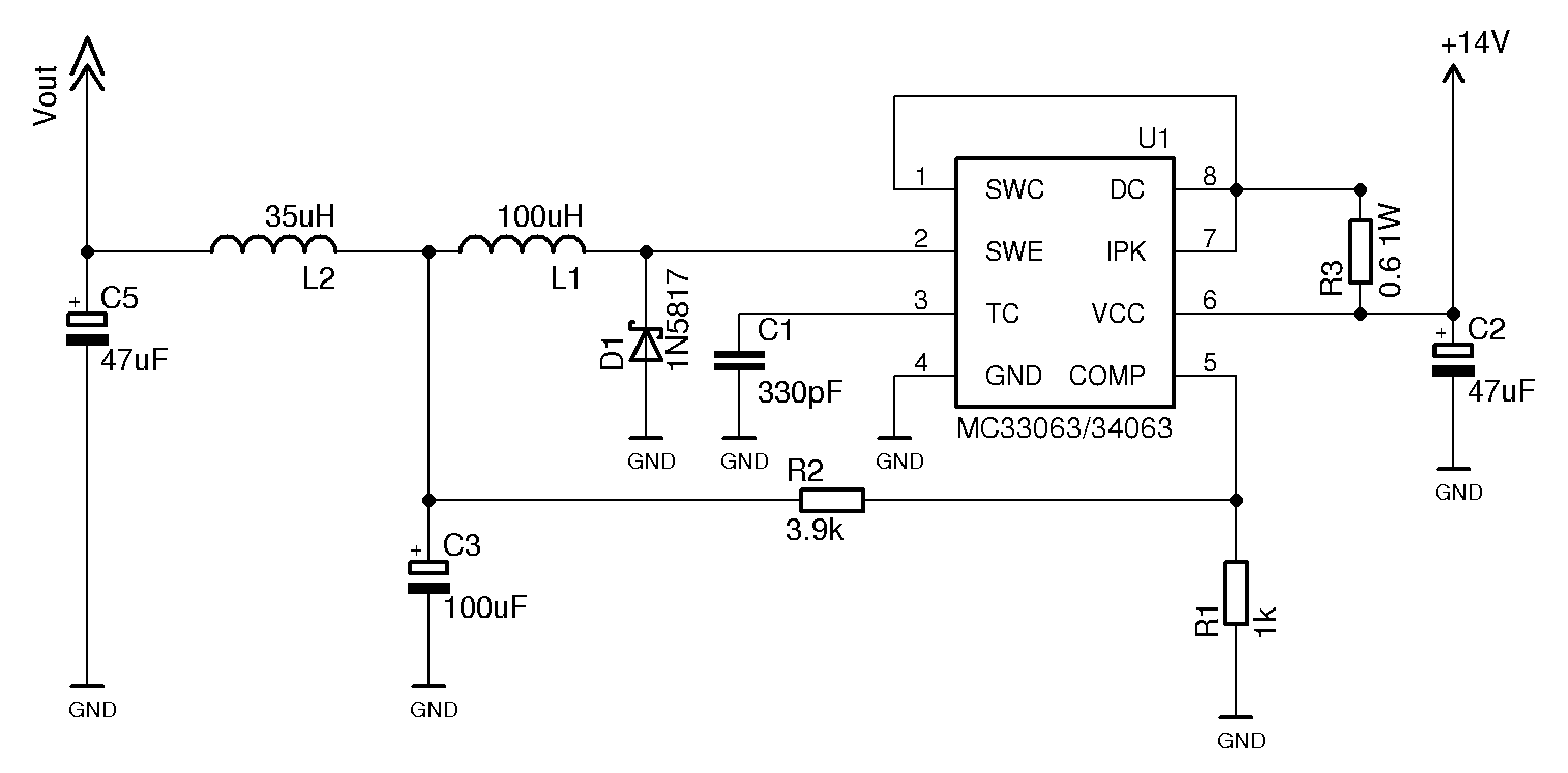
schematic

I've connected it according to the datasheet with an extra LC-filter at the output to reduce rippling. The diode I've used is 1N5817. The circuit is powered from a non-regulated wall wart "9V 500mA" adapter that outputs around 14.5V with no load and drops to 14V when I connect it to the circuit with load. After measuring output voltage I had some strange results:

  • Vout = 4.45V with no load
  • Vout = 3.79V with 10k load
  • Vout = 2.38V with 620 Ohm load

Why is it performing so bad? According to my calculations, Vout is supposed to be around 6.2V and since the converter is capable of delivering relatively high current, there shouldn't be such a huge voltage drop. Or should I use a different (better-performing) converter for this task?

Update: I've just measured the resistance of R2 and.. it was only a few ohms. However the color code is "orange-white-red-gold". Weird. I've checked all the components, but I never thought that something like a 3.9k resistor could malfunction. Wasted many hours because of that resistor :) Anyway, thank you everyone for your effort and patience, it was a silly mistake after all.

\$\endgroup\$
16
  • 1
    \$\begingroup\$ Any chance we can have a look at D1 cathode with a scope, i.e. pin 2 of the chip? If you don't have a scope try to remove your L2-C5 filter and see what happens. \$\endgroup\$ Commented May 30, 2014 at 9:40
  • 1
    \$\begingroup\$ Try with a lower value R3 (in the datasheet says 0.22 ohms). I only got a similar converter working by replacing R3 with a jumper. \$\endgroup\$
    – Cornelius
    Commented May 30, 2014 at 9:41
  • \$\begingroup\$ @VladimirCravero, My diy scope only handles low frequencies :( I've measured the voltage after L1 and it's a few mV higher then Vout. \$\endgroup\$
    – Ashton H.
    Commented May 30, 2014 at 9:57
  • 2
    \$\begingroup\$ No, it should work well. Don't assume that photos of top and bottom of perf board won't help. It may be the only thing that does. \$\endgroup\$ Commented May 30, 2014 at 12:25
  • 1
    \$\begingroup\$ Is there solder flux all over the feedback resistors R1 & R2 or around the IC pins etc? Top of the board looks clean, how about the bottom. The values are low so it might not matter but if they were 100k & 390k it could. \$\endgroup\$
    – Matt B.
    Commented May 30, 2014 at 19:20

2 Answers 2

3
\$\begingroup\$

MC34063 should work well as shown.
Internal switch is not marvellous but good enough in this and many other applications.
I'm wary of the AIC1563 - is pin 8 identical to 34063 - may be but be sure.

Check all connections are as you think.
Use an ohmmeter to ensure adjacent pins and tracks are not shorted.
Use ohmmeter on top of perf board to be sure things are connected as expected.

Ensure timing capacitor is REALLY 330 pF and not something larger.

Short Isense resistor - but you say you did that.

Try small cap across R2 - upper R of voltage divider. 1 NF or less.

Swap IC for another - but probably not the problem.

\$\endgroup\$
0
\$\begingroup\$

The equation for tON = Ct/4e-5 where you have Ct=3.3e-10 thus tON=0.8e-5 and from graph, tOFF=1/5 of tON (@5V). If rise time of switch is much slower than 8us it will perform as a high impedance output, which matches your test results. Since this frequency is ~ 100 kHz and it is good to have f > audio limit, choose Cf to be 5x greater or >1600 pF .

The absolute max switch current is 2A and L = (Vin-Vsat) / I * tON , thus if C=1600pF=1.6e-9 and tON=4e-5 and Vin=9 to 14 with Vce(sat)=0.8max @1A then...

Compute L.

L<=14/2*4e-5= 2.8e-4 or 280uH

Choose 220uH for safety thermal margin and choose L,rated for higher current ( so core does not saturate and drop L) . Your L components do not seem within range for high current, but increasing C will drop f and make it regulate. If too big, the frequency will be audible on the coil. (Nuicance only)

\$\endgroup\$

Your Answer

By clicking “Post Your Answer”, you agree to our terms of service and acknowledge you have read our privacy policy.

Not the answer you're looking for? Browse other questions tagged or ask your own question.