17
\$\begingroup\$

I am a beginner in electronics. I come to know about the oscillator using RC circuits (capacitor charge and discharge and time constant tells the behavior of circuit).

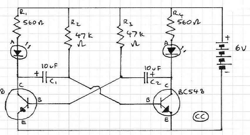
Then I saw the following circuit that blinks 2 LEDs timely in sequence. Will somebody explain its working? I know that capacitor will charge and during charging the LED will be off and when they discharge they will turn on the LED.

But why are the transistors there?

This Circuit will blink LEDs timely

\$\endgroup\$
3
  • \$\begingroup\$ I did some formatting and spelling edits to the post but I am unable to improve on the second paragraph. \$\endgroup\$
    – jpc
    Commented Mar 30, 2011 at 13:39
  • \$\begingroup\$ I have made this but both leds light at the same time.It doesn´t blink.Can someone help me? \$\endgroup\$
    – user9385
    Commented Apr 22, 2012 at 13:53
  • 1
    \$\begingroup\$ I have found an awesome explanation on here. \$\endgroup\$
    – Utku
    Commented Apr 5, 2016 at 13:07

2 Answers 2

18
\$\begingroup\$

This circuit is called an astable multivibrator, and the reason this circuit works is a little difficult to put into words.

Take a look at this circuit simulation that shows visually what is happening. You can slow the speed right down and look carefully at how the current is flowing.

While one of the capacitors is charging, current flows to the base of the alternate transistor, making the emitter-collector path conduct, making one of the LEDs light. When the capacitor is charged, it stops conducting and switches off the transistor, and then the other capacitor begins to charge switching on the other transistor, at the same time the first capacitor discharges, then the cycle repeats.

\$\endgroup\$
2
  • 1
    \$\begingroup\$ Why is the one voltage of the transistors not getting as high as the other? IS that a fault with the simulation as surely they should get to the same with the same resistors and cap sizes. \$\endgroup\$
    – Dean
    Commented Mar 30, 2011 at 18:29
  • 2
    \$\begingroup\$ @Dean: Actually, one of the resistors is 10 ohms less than the other... this is to start the circuit oscillation in the unrealistic world of the simulator. \$\endgroup\$
    – BG100
    Commented Mar 30, 2011 at 19:04
4
\$\begingroup\$

Imagine that R2 were omitted, and suppose the left side transistor (which I'll call Q1) started out being turned on. Then the right side transistor (Q2) would have nothing to turn it on, and the left side transistor would be held on by current through R3, while the R4 and the LED would charge C2. The effect would be that the left LED would come on and stay on, while the right LED would never light.

Now add R2. This will cause C1 to charge to -0.7 volts, until Q2 turns on. Once that happens, the charge on C2 would cause the base of Q1 to go negative, turning it off. When that happens, left-side LED current will start flowing through C1 and the base of Q2, turning it on even harder. Once Q2 has turned on, it will keep Q1 off until C2 charges to -0.7 volts.

Note that while the circuit would have a stable state with both transistors on and both capacitors reverse-biased by 0.7 volts, in practice the winky-blink circuit always starts oscillating rather than entering such a state.
\$\endgroup\$

Not the answer you're looking for? Browse other questions tagged or ask your own question.