2
\$\begingroup\$

I've got a little problem with a board I designed. What I tried to achieve is to control some LEDs with a microcontroller featuring an Arduino bootloader so that you can program it with the Arduino IDE.

As you can see on the picture, I've used an ATmega32U4, and flashed the Arduino Leonardo bootloader (Caterina-Leonardo) onto it, but it wasn't recognized as USB-device when I connected it to my PC (neither under Windows nor under Linux, nor was it recognized at all). Note that some caps between +5V and GND near the microcontroller as well as a cap between VBUS and GND are not shown on the picture but present on the board.
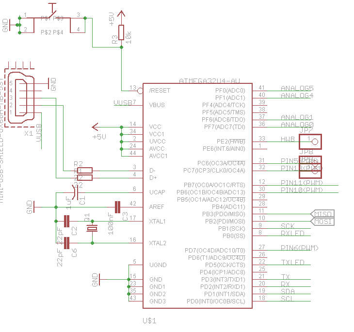
Schematic of the microcontroller

Flashing went without any problems, and the fuses were set just like another project featuring an ATmega32U4 I found on the Internet:
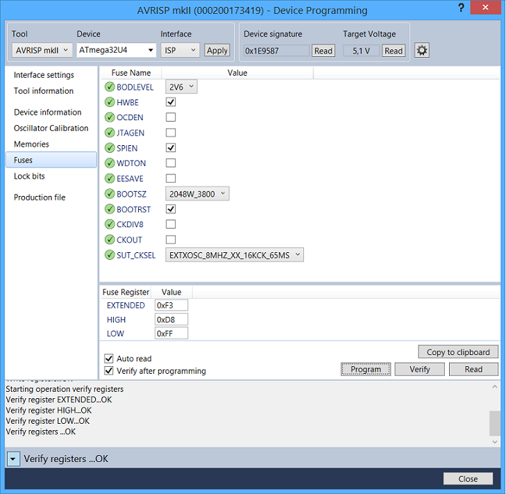
Fuses of the ATmega32U4

So when I measured D+ and D- of the USB-Socket, my oscilloscope showed the following:
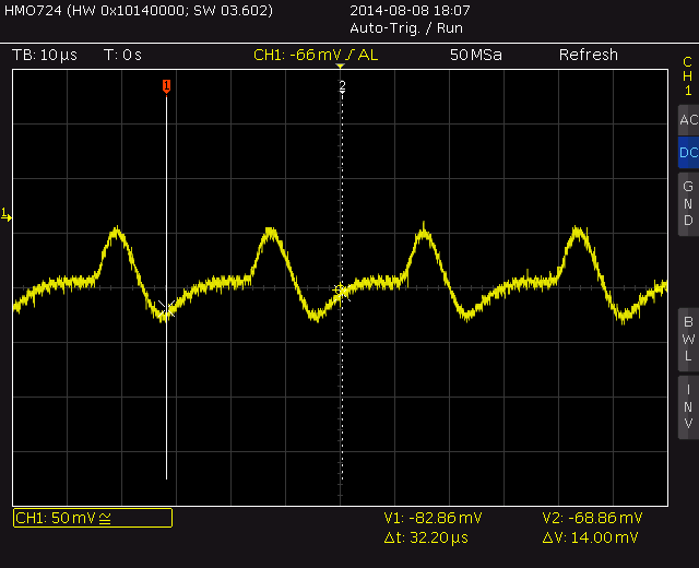
D+/D- of the USB-connector

So obviously something is not working right. By activating the CKOUT-fuse I was able to measure the clock on PIN7, so it seems that the chip does at least something. I then flashed a small example program onto it to set some pins to HIGH, but no matter what pins I choose I always get the following output:
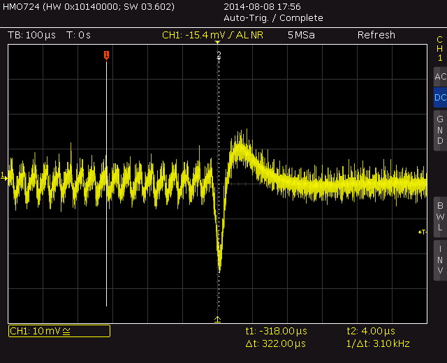
Output from the microcontroller

Does anyone have any idea what is wrong or what I could do? I hope the chip is not dead after all. I also measured the +5V rail but it was very clean, much less noise than a "USB-5V".

I hope I didn't forget something important!

\$\endgroup\$
3
  • \$\begingroup\$ -- Sorry for the comment on decoupling caps, a misunderstanding -- \$\endgroup\$
    – Dzarda
    Commented Aug 9, 2014 at 23:06
  • \$\begingroup\$ Is this on a breadboard or did you have a PCB manufactured? If PCB, did it get a 100% test? \$\endgroup\$
    – RJR
    Commented Aug 10, 2014 at 1:27
  • \$\begingroup\$ It is on a manufactured PCB and completed their tests without any problem. After all I just took my multimeter after I saw the datalines and measured the resistance for every connection of the microcontroller, and at least I can say that everything is connected as it should be \$\endgroup\$ Commented Aug 10, 2014 at 1:44

1 Answer 1

1
\$\begingroup\$

In your second image, the scale is just 10mV. Hence, I would not read too much into that pattern. It's possible that you are just picking up noise. Power supply decoupling caps should not cause you much concern, as long as they are in parallel, and are not blown. Could you provide more detail on how much power the part is drawing when you connect it to the USB port? Does the part overheat?

\$\endgroup\$
3
  • \$\begingroup\$ In the second image the surprising part was that there is no logic signal as you would expect from the data-lines of an USB-connector; that's why I got suspicious and tried the test program. The microcontroller warms up a little bit but nothing seems to overheat. There is also a buck-boost regulator on the board and the whole board (without any LED light up) draws about 90mA-200mA when powered with 5V. \$\endgroup\$ Commented Aug 9, 2014 at 23:21
  • \$\begingroup\$ 200mA sounds high. What else is connected? I've never had a ATMega run even warm without drawing any current on its IO ports. \$\endgroup\$
    – RJR
    Commented Aug 10, 2014 at 1:30
  • \$\begingroup\$ The other components on the board are the buck-boost converter, a dynamic power-path management chip which includes the logic to load a rechargeable battery and the LEDs, as well a LED to signal that there is power. I also measured the current before installing the microcontroller and it was about the same, so I assume the other parts are causing the 200mA. \$\endgroup\$ Commented Aug 10, 2014 at 1:47

Your Answer

By clicking “Post Your Answer”, you agree to our terms of service and acknowledge you have read our privacy policy.

Not the answer you're looking for? Browse other questions tagged or ask your own question.